Product Overview
Functional Definition
The AKH-0.66 series split-core current transformers are precision electromagnetic instruments designed for accurate current measurement, energy metering, and protection applications in low-voltage AC power systems. These transformers feature opening-type (split-core) construction enabling installation without disconnecting primary circuits, utilizing electromagnetic induction principles to provide galvanically isolated secondary current signals proportional to primary current.
Key Ratings Snapshot
| Item | Specification (per order / nameplate) |
|---|---|
| System voltage class | 0.66 kV class (low-voltage distribution applications) |
| Rated frequency | 50 Hz |
| Rated secondary current | 5 A |
| Accuracy classes | Metering and/or protection cores: 0.5 / 1 / 3 |
| Rated burden | Per core/winding as specified (VA) |
| Burden power factor | cosφ = 0.8 (lagging) unless otherwise specified |
| Installation type | Split-core (opening type) for retrofitting existing installations |
| Applicable standards | GB1208-2006; IEC60044-1:2003 and special requirements |
| Model variants | AKH-0.66/23, AKH-0.66/58, AKH-0.66/88, AKH-0.66/812, AKH-0.66/816 |
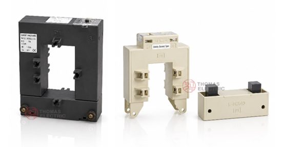
Product Shows

Working Principle
Operating on Faraday’s law of electromagnetic induction, the transformer features a split toroidal magnetic core that can be opened to enclose existing primary conductors without service interruption. The magnetic flux generated by primary current induces proportional voltage in the secondary winding wound around the core, delivering standardized output current through connected burden. The split-core design incorporates precision mating surfaces to maintain magnetic circuit integrity when closed.
System Application Position
- Low-Voltage Distribution: 380V/400V/660V switchgear and distribution panels
- Energy Metering: Electricity measurement and sub-metering systems
- Protection Circuits: Overcurrent and motor protection schemes
- Retrofit Applications: Current monitoring addition to existing installations without service interruption
- Building Management Systems: Energy monitoring and data acquisition
Structural Form Overview
Cast resin insulated construction with split-core opening mechanism ensures superior insulation performance, moisture resistance, and mechanical strength. The enclosed design provides compact installation in constrained panel environments while maintaining excellent electrical clearance. The opening mechanism features secure latching for reliable magnetic circuit closure during operation.
Model Designation

Model Code Explanation
- A — Current transformer (安科瑞 Acrel prefix)
- K — Opening type / split-core construction (开口式)
- H — Mutual inductor / transformer (互感器)
- 0.66 — Voltage class (kV)
- /23, /58, /88, /812, /816 — Window aperture size variant code (installation capacity differences)
Variant Differences
AKH-0.66/23, /58, /88, /812, and /816 variants differ primarily in window aperture dimensions and rated primary current ranges to accommodate different busbar sizes and load capacities. Electrical performance characteristics (accuracy class, rated output) are specified per ordered configuration. Selection depends on primary conductor cross-section and expected current range.
Service Conditions
The AKH-0.66 series current transformers are designed for indoor operation under normal service conditions in low-voltage power systems.
- Installation environment: Indoor installation only
- Altitude: Not exceeding 1000 m above sea level (higher altitude shall be specified for engineering confirmation)
- Ambient temperature: −5 °C to +40 °C
- Relative humidity: Daily average ≤ 95%, monthly average ≤ 90%
- Environmental conditions: Free from corrosive gases or vapors; free from explosive or flammable media; no severe vibration, mechanical shock, or impact
Construction
Construction Design
- Structure: Split-core (opening type) for retrofit installation without primary circuit interruption
- Insulation: Enclosed cast resin insulation system
- Core: Split ring-type magnetic core with precision mating surfaces
- Mechanism: Secure latching system for reliable core closure
- System: Integrated primary and secondary insulation
The cast resin construction provides stable insulation properties and resistance to moisture, contamination, and aging for long-term indoor service. The split-core mechanism enables installation on energized circuits where service interruption is impractical.
Windings & Terminal Marking
- Primary terminals: P1 / P2 (or through-busbar aperture)
- Secondary terminals (Group 1): S1 / S2
Terminal markings follow standard CT polarity conventions. Under normal operating conditions, the reference current direction is defined from P1 to P2. Correct terminal identification and core closure shall be observed to ensure metering and protection performance.
Technical Data
This section provides selection-oriented technical data for the AKH-0.66 series indoor, split-core current transformer used in 0.66 kV class AC systems (50 Hz). Data shown below is intended for preliminary selection of accuracy class combinations, rated burdens, and window aperture sizing.
Definitions: Accuracy class indicates metering or protection core accuracy per IEC/GB standards. Rated output (VA) is specified per accuracy class. Window aperture dimensions determine maximum primary conductor size that can pass through the opening.
Data Reference
AKH-0.66/23
| Rated Primary Current (A) | Accuracy Class-Rated Output (VA) | Packing | ||
|---|---|---|---|---|
| 0.5 | 1 | 3 | ||
| 100/5 | — | — | 1.5 | 20PCS 36×31.5×26cm 20.5kg |
| 150/5 | — | — | 2 | |
| 200/5 | — | 1.5 | 2.5 | |
| 250/5 | — | 2.5 | 3.75 | |
| 300/5 | 1.5 | 2.5 | 6 | |
| 400/5 | 2.5 | 3.75 | 10 | |
AKH-0.66/58
| Rated Primary Current (A) | Accuracy Class-Rated Output (VA) | Packing | ||
|---|---|---|---|---|
| 0.5 | 1 | 3 | ||
| 300/5 | — | 1.5 | 3.75 | 10PCS 42×30×20cm 12kg |
| 400/5 | — | 2.5 | 5 | |
| 500/5 | 1.5 | 2.5 | 10 | |
| 600/5 | 2.5 | 5 | 15 | |
| 750/5 | 3.5 | 5 | 20 | |
| 800/5 | 3.75 | 5 | 20 | |
| 1000/5 | 5 | 10 | 20 | |
AKH-0.66/88
| Rated Primary Current (A) | Accuracy Class-Rated Output (VA) | Packing | ||
|---|---|---|---|---|
| 0.5 | 1 | 3 | ||
| 250/5 | — | 1.5 | 3.75 | 10PCS 42×37×20cm 14kg |
| 300/5 | — | 1.5 | 5 | |
| 400/5 | — | 2.5 | 10 | |
| 500/5 | 1.5 | 2.5 | 15 | |
| 600/5 | 2.5 | 5 | 15 | |
| 750/5 | 2.5 | 5 | 20 | |
| 800/5 | 3.75 | 5 | 20 | |
| 1000/5 | 5 | 7.5 | 20 | |
AKH-0.66/812
| Rated Primary Current (A) | Accuracy Class-Rated Output (VA) | Packing | ||
|---|---|---|---|---|
| 0.5 | 1 | 3 | ||
| 500/5 | — | 2.5 | 12.5 | 10PCS 43×38×24cm 16kg |
| 600/5 | — | 2.5 | 15 | |
| 750/5 | 2.5 | 5 | 12.5 | |
| 800/5 | 2.5 | 5 | 20 | |
| 1000/5 | 3.75 | 7.5 | 20 | |
| 1200/5 | 5 | 10 | 25 | |
| 1250/5 | 5 | 10 | 30 | |
| 1500/5 | 7.5 | 10 | 30 | |
| 1600/5 | 7.5 | 10 | 30 | |
| 2000/5 | 7.5 | 15 | 30 | |
AKH-0.66/816
| Rated Primary Current (A) | Accuracy Class-Rated Output (VA) | Packing | ||
|---|---|---|---|---|
| 0.5 | 1 | 3 | ||
| 1000/5 | 5 | 10 | 20 | 5PCS 52.5×30×23cm 19kg |
| 1200/5 | 7.5 | 10 | 25 | |
| 1600/5 | 7.5 | 10 | 25 | |
| 2000/5 | 10 | 15 | 25 | |
| 2500/5 | 15 | 20 | 25 | |
| 3000/5 | 20 | 25 | 30 | |
| 4000/5 | 20 | 25 | 30 | |
| 5000/5 | 20 | 25 | 30 | |
Standards & Normative References
| Standard | Title | Application |
|---|---|---|
| GB1208-2006 | Current Transformers | National standard for current transformers |
| IEC60044-1:2003 | Instrument Transformers – Part 1: Current Transformers | International CT requirements and special demands |
| GB/T 20840.2 | Instrument Transformers – Part 2: Current Transformers | National CT requirements (aligned with IEC framework) |
Factory Testing Compliance
- Routine tests per applicable IEC/GB requirements (including polarity/marking, ratio verification, and accuracy verification per specified class and burden)
- Dielectric tests per insulation coordination requirements and applicable standard
- Visual and dimensional inspection including marking and workmanship conformity
- Type and special tests as required by the project specification
Installation & Dimensions


Installation Procedure
- Verify primary conductor size compatibility with selected model window aperture
- Open the split-core mechanism by releasing the latching system
- Position the transformer around the primary conductor ensuring proper polarity orientation (P1 to P2 direction)
- Close the split-core ensuring complete magnetic circuit engagement with secure latching
- Connect secondary terminals to metering or protection devices observing correct polarity (S1/S2)
- Verify installation clearances and mounting security
Dimensional Reference
AKH-0.66/23 Overall Dimensions
Window aperture: 21mm × 32mm | Overall: 89mm × 111mm × 60mm
AKH-0.66/58, /88, /812, /816 Overall Dimensions
| Model | a (mm) | b (mm) | A (mm) | B (mm) | C (mm) | D (mm) | H (mm) |
|---|---|---|---|---|---|---|---|
| AKH-0.66/58 | 82 | 51 | 146 | 115 | 78 | 49 | 148 |
| AKH-0.66/88 | 82 | 80 | 146 | 146 | 110 | 49 | 148 |
| AKH-0.66/812 | 122 | 80 | 188 | 146 | 110 | 49 | 190 |
| AKH-0.66/816 | 164 | 80 | 246 | 184 | 120 | 69 | 248 |
Notation: a = window aperture width; b = window aperture height; A, B, C, D, H = overall external dimensions per model-specific configuration.
Safety Notes
- Secondary circuit must never be left open when the transformer is energized, as dangerous high voltage may appear across the secondary terminals
- During inspection or maintenance, the secondary circuit shall be short-circuited before disconnecting any instruments
- One point of the secondary circuit should be reliably grounded in accordance with applicable standards
- Ensure complete core closure and secure latching before energizing to maintain accuracy and prevent magnetic saturation
- All installation and maintenance work shall comply with local electrical safety regulations
Ordering Information
When placing an order, the required configuration shall be specified according to the local distribution system requirements, applicable standards, and project technical specification. The following parameters shall be clearly stated for technical confirmation and production release:
- Model designation (AKH-0.66/23, /58, /88, /812, or /816)
- Rated primary current / transformation ratio
- Rated secondary current (5 A standard)
- Accuracy class requirements (0.5 / 1 / 3)
- Rated burden (VA) per accuracy class
- Quantity and delivery requirements
Selection Guidelines
- Determine rated primary current (Ip) based on feeder/load rating and expected operating range
- Select model variant based on primary conductor cross-section and window aperture requirements
- Select accuracy class based on application (0.5 for revenue metering; 1 or 3 for indication/protection)
- Confirm rated burden (VA) based on connected meters/relays and wiring losses
- Verify physical dimensions and mounting constraints at installation location
If local utility or project requirements apply (e.g., special accuracy verification, terminal arrangement, mounting constraints, documentation language, or required certificates), specify them at the ordering stage. Special configurations shall be confirmed by technical agreement and final data sheet prior to production.
FAQs
Q1: What is the advantage of split-core current transformers for low-voltage applications?
A: Split-core CTs enable installation on existing energized circuits without service interruption or primary conductor disconnection, ideal for retrofit metering and monitoring applications in operational facilities.
Q2: How to select the correct model variant based on primary conductor size?
A: Select model variant based on window aperture dimensions that accommodate the primary busbar or cable cross-section with adequate clearance. Refer to dimensional tables for aperture size (a × b) per model.
Q3: How are accuracy classes specified for low-voltage current transformers (IEC60044-1 / GB1208)?
A: Accuracy classes (0.5, 1, 3) indicate measurement error limits under specified burden and operating conditions. Class 0.5 is specified for revenue-grade metering; Class 1 or 3 for indication and protection applications.
Q4: How to determine rated burden (VA) for 5A CT secondary circuits?
A: Rated burden (VA) shall cover total connected load (meter/relay power consumption + wiring impedance loss) at 5A secondary current. Burden shall be confirmed during engineering design with adequate margin.
Q5: What are the critical installation requirements for split-core transformers?
A: Ensure complete core closure with secure latching, observe correct polarity orientation (P1/P2, S1/S2), verify conductor centering in window aperture, and confirm secondary grounding per applicable standards.
Q6: Are AKH-0.66 variants suitable for 400V/660V three-phase distribution systems?
A: Yes. Rated system voltage 0.66kV covers 400V/660V distribution applications. Select appropriate current ratio based on per-phase conductor rating and expected load current.
Q7: What are mandatory secondary handling requirements for split-core CTs?
A: Do not open-circuit CT secondary under energized primary. Short-circuit and ground secondary per project practice before disconnection. Observe terminal polarity marks S1/S2 for correct meter/relay connection.
Q8: Which documents govern compliance (IEC/GB standards, traceability)?
A: Nameplate and factory test report prevail. Compliance to GB1208-2006 and IEC60044-1:2003 confirmed by routine testing. Unit test certificates are traceable to manufacturer quality records.