1. Product Overview
1.1 Functional Definition
The LQZJ-0.66 is a single-ratio, single-phase, indoor-type current transformer (CT) rated for 0.66 kV class low-voltage AC distribution networks at 50 Hz or 60 Hz. The device transforms primary current — flowing through the central Ø103 mm aperture by way of a busbar or insulated cable — into a galvanically isolated secondary current of 5 A, scaled to the nameplate ratio. The secondary signal feeds energy meters, ammeters, transducers, or overcurrent / thermal protection relays, providing electrical isolation between the high-current primary circuit and the instrumentation circuit.
1.2 Key Ratings Snapshot
| Parameter | Specification |
|---|---|
| System voltage class (Um) | 0.72 kV (rated for 0.66 kV / 660 V systems) |
| Rated frequency (fr) | 50 Hz or 60 Hz |
| Rated primary current (I₁n) | 5, 10, 15, 20, 30, 40, 50, 75, 100, 150, 200, 300, 400, 600, 800, 1000 A |
| Rated secondary current (I₂n) | 5 A standard (1 A available on request) |
| Accuracy class | 0.2, 0.5, 1 (metering); 10P (protection) |
| Rated output (Sn) | 10 VA at class 0.2/0.5; 15 VA at class 1/10P (per nameplate) |
| Rated short-time thermal current (Ith) | 50 × I₁n for 1 s |
| Rated dynamic current (Idyn) | 100 × I₁n peak |
| Burden power factor | cos φ = 0.8 lagging (default per IEC 61869-2) |
| Insulation system | Epoxy resin vacuum cast, fully enclosed; thermal class B (130 °C) or higher |
| Primary aperture | Ø103 mm |
| Overall dimensions | 140 mm (W) × 127.5 mm (H) × 103 mm (D) |
| Standards | IEC 61869-1, IEC 61869-2, GB/T 20840.1, GB/T 20840.2, GB 1208 |
| Predecessor | Direct replacement for legacy LQG-0.5 series |

1.3 Working Principle
The LQZJ-0.66 operates as a single-turn primary, multi-turn secondary, ring-core current transformer governed by Faraday’s law of electromagnetic induction and Ampère’s circuital law. The primary conductor passes once through the toroidal core; the secondary winding consists of N₂ turns evenly distributed around the core circumference. Under steady-state sinusoidal excitation, the ideal current relationship is:
The secondary current driven through the connected burden Zb develops a secondary EMF that magnetises the core. Real CTs deviate from the ideal ratio by a current error εi and a phase displacement δ, both arising from the magnetising current Iμ required to sustain the working flux. The composite error ε at the rated accuracy limit factor (ALF) defines the protection class accuracy, expressed as:
where Kn is the rated transformation ratio. For metering classes (0.2, 0.5, 1), εi and δ are bounded at 100% I₁n by IEC 61869-2 Table 201; for protection class 10P, the composite error ε is bounded to ≤ 10% at the accuracy limit current (ALF × I₁n).
1.4 System Application Position
- Low-voltage switchgear
- 380 V / 400 V / 415 V / 690 V switchboards, distribution panels, motor control centres (MCCs), and ATS panels feeding industrial and commercial loads.
- Energy metering
- Revenue-grade kWh/kvarh metering (class 0.2 / 0.5), sub-metering for tenant billing, and check-metering for utility tie points.
- Process measurement
- Ammeter input for HMI/SCADA, transducer input (4–20 mA / Modbus), and load profiling for power-quality analysis.
- Relay protection
- Overcurrent (51), instantaneous overcurrent (50), thermal overload (49), motor protection, and earth-fault protection (51N) where the LQZJ is dedicated to phase current acquisition (separate residual CT for ground fault).
- Building & energy management
- Input device for BMS, EMS, and ISO 50001 energy-monitoring systems requiring isolated current acquisition.
1.5 Structural Form Overview
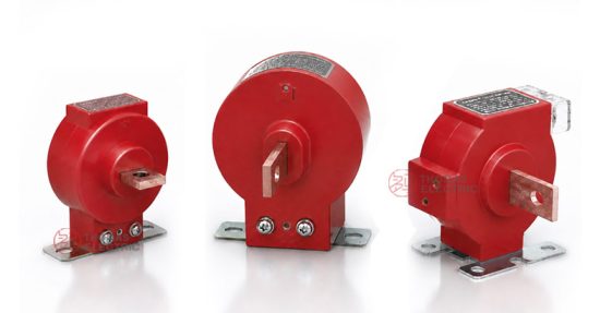
Compact post-type construction with epoxy-resin-encapsulated core-and-coil assembly inside a flame-retardant moulded housing. The 140 × 127.5 mm footprint and Ø103 mm window are dimensioned to accept standard low-voltage switchgear busbars (typically 50 × 5 mm to 100 × 10 mm) or 3-core / single-core cables up to ~95 mm bundle diameter. Dual mounting interfaces — bottom panel or side panel — each with selectable 2-hole or 4-hole fixing patterns, provide installation flexibility across cubicle layouts. The fully enclosed cast-resin body delivers IP20 ingress protection (higher with auxiliary covers), eliminates exposed live parts, and ensures stable dielectric and partial-discharge performance over the full thermal class B (or F on request) life.
2. Model Designation & Variants

2.1 Model Code Explanation
The LQZJ-0.66 designation follows the GB/JB Chinese instrument-transformer naming convention. Each character encodes a specific construction or rating attribute:
| Character | Position | Meaning |
|---|---|---|
| L | 1 | Current transformer (电流互感器) |
| Q | 2 | Toroidal / ring-wound construction (浇圈式) |
| Z | 3 | Cast-resin (epoxy) insulated, fully enclosed (浇注绝缘) |
| J | 4 | Increased capacity / enhanced output (加大容量) |
| □ | 5 | Design sequence number (manufacturer iteration code) |
| 0.66 | suffix | Rated voltage class in kV (0.66 kV / 660 V) |
2.2 Standard Variant Matrix
The LQZJ-0.66 is offered in multiple electrical configurations, each defined by primary current, accuracy class, and rated output. All variants share the same mechanical envelope and Ø103 mm aperture, allowing a single switchgear cutout to accept any electrical specification.
| Configuration
ID |
Primary
current I₁n (A) |
Accuracy
class |
Rated output
Sn (VA) |
Typical
use |
|---|---|---|---|---|
| M1 | 5–100 | 0.5 | 10 | Sub-metering, ammeter |
| M2 | 50–600 | 0.5 | 10 | Distribution metering |
| M3 | 100–1000 | 0.2 | 10 | Revenue metering |
| M4 | 50–1000 | 1 | 15 | General current measurement |
| P1 | 50–1000 | 10P | 15 | Overcurrent / thermal protection |
2.3 Series Evolution
The LQZJ-0.66 supersedes the legacy LQG-0.5 series introduced in earlier GB design generations. Mechanical envelope, mounting interface, and primary aperture (Ø103 mm) are fully backward-compatible. Engineering improvements over the predecessor include: upgraded epoxy resin formulation with improved thermal endurance and reduced partial-discharge inception voltage variability; refined core grain orientation for lower magnetising current at low primary excitation; and tighter accuracy banding across the 25–120% I₁n metering range.
3. Service Conditions
The LQZJ-0.66 is qualified for indoor service per IEC 61869-1 clause 4 normal service conditions. Operation outside the limits below requires engineering review and may necessitate derating, alternative insulation class, or special configuration.
| Parameter | Standard | Extended
(on request) |
|---|---|---|
| Installation | Indoor only | Indoor + IP-uprated enclosure |
| Altitude | ≤ 2000 m a.s.l. | ≤ 4000 m (with insulation re-rating per IEC 61869-1 cl. 4.2) |
| Ambient temperature | −5 °C to +40 °C | −25 °C to +55 °C |
| Relative humidity | ≤ 95% daily average / ≤ 90% monthly average (non-condensing) | Tropical (condensing) — special coating required |
| Atmosphere | Free from corrosive gases, conductive dust, explosive media | Marine / chemical — special enclosure |
| Vibration | ≤ 0.5 g, no severe shock | Seismic class S2/S3 per IEC 60068-3-3 |
| Pollution degree | PD 2 per IEC 60664-1 | PD 3 — increased clearance required |
4. Construction
4.1 Construction Design
- Magnetic core
- Toroidal (ring-type) wound from grain-oriented silicon steel (CRGO, typically 0.30 mm or 0.27 mm thickness). Core annealed after winding to relieve mechanical stress and restore magnetic permeability. For low-current ranges (I₁n ≤ 50 A), nickel-iron alloy cores may be specified for improved low-end accuracy.
- Primary circuit
- Single-turn pass-through configuration. The Ø103 mm aperture accepts a busbar or cable as the primary “winding”. No dedicated primary terminals; the user-supplied conductor passes through the window in the direction marked P1 → P2 on the housing.
- Secondary winding
- Multi-turn copper magnet wire (Class B or Class F enamel insulation) wound uniformly around the core. Number of secondary turns N₂ equals the rated transformation ratio (e.g., 200/5 → N₂ = 40). Inter-turn insulation and mechanical reinforcement are integrated into the winding assembly before encapsulation.
- Insulation system
- Vacuum-cast epoxy resin fully encapsulates the core-and-coil assembly. The cast body integrates primary-to-secondary insulation, secondary-to-ground insulation, mechanical support, and environmental protection in a single monolithic structure. Standard thermal class is B (130 °C); class F (155 °C) available on request.
- Housing
- Flame-retardant thermoplastic outer shell (UL94 V-0) over the cast-resin body, providing mechanical protection during handling and IP20 ingress protection in service.
- Mounting base
- Integrated polymer base with two interface options: bottom mounting (footprint suitable for panel-floor fixing) or side mounting (suitable for vertical busbar installations). Each base offers either 2-hole or 4-hole fixing patterns; M6 hardware is standard.
- Terminals
- Secondary terminals S1 and S2 are stud-type (M5 or M6 brass) with locking nuts and washers, located on the front face. Polarity is permanently marked on the housing in compliance with IEC 61869-2 cl. 6.13 (primary P1/P2 corresponds to secondary S1/S2 in subtractive convention).
4.2 Windings & Terminal Marking
| Terminal | Designation | Function |
|---|---|---|
| P1 | Primary, polarity-marked end | Conventional current entry; reference direction for ratio test |
| P2 | Primary, non-polarity end | Conventional current exit |
| S1 | Secondary, polarity-marked end | Output to ammeter / meter / relay positive input |
| S2 | Secondary, non-polarity end | Output to instrumentation neutral; one-point earthed in service |
Reference current direction: when primary current i₁ enters at P1 and exits at P2, secondary current i₂ flows out of S1, through the external burden, and returns at S2. This subtractive polarity is mandatory for correct kWh metering, watt-metric earth-fault protection, and any directional relay function.
5. Technical Data
This section provides selection-grade electrical data for the LQZJ-0.66 series. All values apply at the rated burden and rated frequency as marked on the nameplate. For configurations outside the standard ranges, technical agreement and a project-specific datasheet shall govern.
5.1 Primary & Secondary Ratings
| Rated primary
current I₁n (A) |
Rated secondary
current I₂n (A) |
Available
accuracy class |
Rated
output Sn (VA) |
Ith / 1 s
(kA) |
Idyn peak
(kA) |
|---|---|---|---|---|---|
| 5 | 5 | 0.5 / 1 | 10 / 15 | 0.25 | 0.5 |
| 10 | 5 | 0.5 / 1 | 10 / 15 | 0.5 | 1.0 |
| 15 | 5 | 0.5 / 1 | 10 / 15 | 0.75 | 1.5 |
| 20 | 5 | 0.5 / 1 | 10 / 15 | 1.0 | 2.0 |
| 30 | 5 | 0.5 / 1 | 10 / 15 | 1.5 | 3.0 |
| 40 | 5 | 0.5 / 1 | 10 / 15 | 2.0 | 4.0 |
| 50 | 5 | 0.2 / 0.5 / 1 / 10P | 10 / 15 | 2.5 | 5.0 |
| 75 | 5 | 0.2 / 0.5 / 1 / 10P | 10 / 15 | 3.75 | 7.5 |
| 100 | 5 | 0.2 / 0.5 / 1 / 10P | 10 / 15 | 5.0 | 10 |
| 150 | 5 | 0.2 / 0.5 / 1 / 10P | 10 / 15 | 7.5 | 15 |
| 200 | 5 | 0.2 / 0.5 / 1 / 10P | 10 / 15 | 10 | 20 |
| 300 | 5 | 0.2 / 0.5 / 1 / 10P | 10 / 15 | 15 | 30 |
| 400 | 5 | 0.2 / 0.5 / 1 / 10P | 10 / 15 | 20 | 40 |
| 600 | 5 | 0.2 / 0.5 / 1 / 10P | 10 / 15 | 30 | 60 |
| 800 | 5 | 0.2 / 0.5 / 1 / 10P | 10 / 15 | 40 | 80 |
| 1000 | 5 | 0.2 / 0.5 / 1 / 10P | 10 / 15 | 50 | 100 |
Note: 1 A secondary configurations available on request; consult factory for non-standard ratios.
5.2 Accuracy Class Limits (per IEC 61869-2)
| Class | Current at which
accuracy applies |
Current error
εi (±%) |
Phase displacement
δ (±min) |
Composite error
ε at ALF |
|---|---|---|---|---|
| 0.2 | 5%, 20%, 100%, 120% I₁n | 0.75 / 0.35 / 0.20 / 0.20 | 30 / 15 / 10 / 10 | — |
| 0.5 | 5%, 20%, 100%, 120% I₁n | 1.5 / 0.75 / 0.50 / 0.50 | 90 / 45 / 30 / 30 | — |
| 1 | 5%, 20%, 100%, 120% I₁n | 3.0 / 1.5 / 1.0 / 1.0 | 180 / 90 / 60 / 60 | — |
| 10P | At I₁n | ±3.0 (current error) | not specified | ≤ 10% at ALF × I₁n |
For class 0.2 and 0.5, accuracy is verified across 25%–100% of rated burden and 5%–120% of rated current. The accuracy limit factor (ALF) for protection class 10P is typically 5, 10, 15, 20, or 30 — specified on the nameplate as e.g. “10P10” (composite error ≤ 10% at 10 × I₁n).
5.3 Thermal & Dynamic Withstand
The short-time thermal current Ith (1 s) and dynamic peak current Idyn are governed by the relations:
For LQZJ-0.66, standard ratings are Ith = 50 × I₁n / 1 s and Idyn = 100 × I₁n peak. Both must equal or exceed the system prospective short-circuit current Ipsc and peak fault current Ipk at the installation point. Verification is by factory short-circuit type-test report referenced on the routine-test certificate.
6. Standards & References
6.1 Applicable Standards
| Standard | Title | Application |
|---|---|---|
| IEC 61869-1 | Instrument Transformers — Part 1: General Requirements | General electrical, mechanical, thermal requirements |
| IEC 61869-2 | Instrument Transformers — Part 2: Additional Requirements for Current Transformers | CT-specific accuracy, burden, short-circuit, type tests |
| GB/T 20840.1 | Instrument Transformers — Part 1: General Requirements | National standard, harmonised with IEC 61869-1 |
| GB/T 20840.2 | Instrument Transformers — Part 2: Current Transformers | National standard, harmonised with IEC 61869-2 |
| GB 1208 | Current Transformers | National CT standard (legacy reference where specified) |
| IEC 60664-1 | Insulation Coordination for Equipment Within Low-Voltage Systems | Clearance and creepage for 0.66 kV class |
| IEC 60529 | Degrees of Protection (IP Code) | Ingress protection rating |
| IEC 60085 | Electrical Insulation — Thermal Evaluation and Designation | Thermal class B / F designation |
| IEEE C57.13 | Standard Requirements for Instrument Transformers | Optional reference for North American projects |
6.2 Routine Tests (Each Unit)
Performed on every manufactured unit per IEC 61869-2 cl. 7.3 / GB/T 20840.2:
- Marking verification (P1/P2, S1/S2, nameplate data)
- Power-frequency withstand voltage test on primary winding (3 kV r.m.s. for 1 minute, 0.66 kV class)
- Power-frequency withstand voltage test on secondary winding (3 kV r.m.s. for 1 minute)
- Inter-turn overvoltage test on secondary
- Determination of errors at rated burden (current error εi and phase displacement δ across 5%–120% I₁n for metering class; composite error at ALF for protection class)
- Polarity verification (P1–S1 subtractive convention)
- Insulation resistance ≥ 100 MΩ at 500 V DC
6.3 Type Tests (Design Validation)
Performed on representative samples per IEC 61869-2 cl. 7.2:
- Temperature rise test at rated continuous current (limits per insulation class)
- Short-time current test (Ith for 1 s) and dynamic current test (Idyn peak)
- Lightning impulse withstand voltage test (8 kV peak, 1.2/50 μs, for 0.72 kV Um class)
- Determination of errors at limit burden conditions
- Verification of accuracy class extended over the full operating range
- Mechanical and environmental tests where specified by project
7. Installation & Dimensions

7.1 Outline Dimensions
| Dimension | Value | Reference |
|---|---|---|
| Overall width | 140 mm (max.) | front view |
| Overall height | 127.5 mm | front view |
| Overall depth | 103 mm (approximate) | side view |
| Primary aperture | Ø103 mm | central window |
| Mounting base length | 110 mm | fixing interface |
| Mounting hole spacing | 56 mm × 89 mm (typical, refer to certified drawing) | 2-hole / 4-hole pattern |
| Mounting hardware | 4 × Ø5 fixing slots; M6 hardware recommended | per variant |
| Net weight | ~ 0.8–1.2 kg (depending on configuration) | shipping reference |
Refer to the certified dimensional drawing for project-specific tolerances and mounting hole coordinates.
7.2 Installation Guidelines
- Mount the CT on a clean, flat, rigid surface using all designated fixing holes. Tighten fasteners to manufacturer-recommended torque (typically 6–8 N·m for M6 hardware).
- Pass the primary conductor (busbar or cable) centrally through the Ø103 mm aperture. Maintain the marked direction P1 → P2 — current flowing in this direction yields S1 → S2 secondary output.
- Ensure adequate clearance to adjacent live parts per the system insulation coordination (minimum 25 mm air clearance for 0.66 kV class per IEC 60664-1, PD 2).
- Size secondary wiring to limit total secondary loop resistance such that the burden remains within Sn at rated current. For 5 A secondary, 2.5 mm² copper for runs up to 25 m is typical; longer runs may require 4 mm² or upgrading to 1 A secondary.
- Connect S1 to the ammeter / meter / relay live input; connect S2 to the instrumentation neutral. Earth one point of the secondary circuit (typically at the protection panel terminal block) — never multiple points.
- Verify polarity and ratio at commissioning using primary injection or polarity tester before energising the primary circuit.
7.3 Safety & Maintenance Notes
- Always short-circuit S1–S2 before disconnecting downstream instrumentation.
- One point of the secondary loop shall be earthed (typically S2 at the marshalling kiosk).
- The primary conductor shall be installed and supported externally — the LQZJ-0.66 housing is not rated to support primary conductor weight or fault-driven mechanical forces.
- Operating CTs at primary current beyond the nameplate Ith / Idyn ratings during faults will cause permanent magnetic, mechanical, or insulation damage.
- All work shall comply with IEC 60364, GB 26860, NFPA 70E, or the applicable local electrical safety code, including lockout / tagout procedures.
8. Selection Guide (Worked Example)
The following four-step procedure illustrates the selection of an LQZJ-0.66 for a representative application: a 250 A continuous load motor feeder in a 400 V switchboard, with a connected digital multifunction meter and a thermal overload relay, located in a building with 20 m of secondary cable run between the switchboard and the metering kiosk.
Step 1 — Determine rated primary current I₁n
Continuous load current Ic = 250 A. Choose I₁n ≥ 1.2 × Ic = 300 A. Selecting from the standard list: I₁n = 300 A. This places the operating point at 250/300 = 83% of I₁n, well within the 25%–100% optimal accuracy band.
Step 2 — Specify accuracy class
The application requires sub-billing-grade metering — class 0.5 per IEC 61869-2 is appropriate. The thermal relay can share the same metering core in this case (the relay’s accuracy demand of class 1 is automatically satisfied by class 0.5). For a stricter installation, a separate 10P core would be specified.
Step 3 — Calculate required burden
Connected loads on the secondary loop:
- Multifunction meter input: Sm = 0.05 VA (typical electronic)
- Thermal overload relay: Sr = 0.5 VA
- Secondary cable: 20 m × 2 (loop) = 40 m total path; 2.5 mm² copper at ρ = 0.0175 Ω·mm²/m → Rwire = 0.0175 × 40 / 2.5 = 0.28 Ω
- Wire burden Sw = I₂n² × Rwire = 5² × 0.28 = 7.0 VA
Selecting Sn = 10 VA at class 0.5 provides 32% margin, which is sufficient. If the cable run exceeded 30 m, the wire burden would push Sb close to 10 VA — in that case, upsize to 4 mm² cable, or specify 1 A secondary to reduce wire burden by a factor of 25.
Step 4 — Verify short-circuit withstand
System prospective fault current at the switchboard busbar: Ipsc = 25 kA / 1 s. For I₁n = 300 A, the CT’s nameplate Ith = 50 × 300 = 15,000 A = 15 kA / 1 s. This is insufficient. The selected CT must be specified with an enhanced Ith rating (factory option), or the upstream protection clearing time must reduce the equivalent 1-s thermal current to within 15 kA. Recalculating: if breaker clearing time tf = 0.3 s, then Ith,equiv = 25 × √0.3 = 13.7 kA — within the standard rating. Confirm the upstream device’s actual let-through I²t against the CT nameplate.
9. Ordering Information
Each order shall specify the parameters below to enable production release and acceptance. Where the project requires non-standard configuration (extended temperature, alternative thermal class, tropicalisation, special terminal layout, language-specific nameplate), state these explicitly at the enquiry stage; they will be fixed by technical agreement and a project-specific datasheet.
| Required parameter | Format / options |
|---|---|
| Model | LQZJ-0.66 |
| Rated primary current I₁n | 5, 10, 15, 20, 30, 40, 50, 75, 100, 150, 200, 300, 400, 600, 800, 1000 A |
| Rated secondary current I₂n | 5 A (standard) / 1 A (on request) |
| Accuracy class | 0.2 / 0.5 / 1 / 10P (specify ALF for 10P, e.g., 10P10) |
| Rated output Sn | 10 VA / 15 VA |
| Number of secondary cores | 1 (single core); 2 (separate metering + protection cores) on request |
| Mounting type | Bottom mount / Side mount |
| Mounting hole pattern | 2-hole / 4-hole |
| Frequency | 50 Hz / 60 Hz |
| Special requirements | Insulation class F, tropicalisation, language of nameplate, third-party witness testing, etc. |
10. FAQs