Article Content
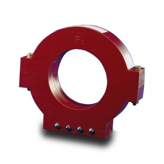
KZB-0 33kV Cast-Resin Current Transformer for Substation Metering and Protection – IEC 61869-2 Certified
Introduction to the KZB-0 Current Transformer
The KZB-0 is a 33kV (IEC-rated) / 35kV (domestic system equivalent) cast-resin current transformer engineered for high-accuracy metering and dependable protective relaying in medium-voltage substations and industrial power networks. Unlike legacy oil-immersed designs, the KZB-0 employs vacuum pressure impregnation (VPI) epoxy resin insulation technology, eliminating fire hazards, oil leakage risks, and maintenance-intensive sealing systems. This design ensures long-term dielectric stability under thermal cycling, pollution, and mechanical stress—critical for outdoor or indoor installations across diverse climatic zones.
Operating Principle of Cast-Resin Insulation
Cast-resin insulation in the KZB-0 utilizes a two-component cycloaliphatic epoxy resin system cured under vacuum and pressure. This process fully encapsulates the primary conductor, secondary windings, and magnetic core—typically fabricated from grain-oriented electrical steel (GOES)—within a monolithic, void-free solid matrix. The absence of air pockets prevents partial discharge inception below 10 pC at 1.2 × Ur (rated voltage), per IEC 61869-2 requirements. The resin’s high tracking resistance (>600 V according to IEC 60112) and hydrophobic surface inhibit flashover in coastal or industrial environments with salt fog or chemical contamination. Thermal conductivity of ~0.8 W/m·K enables efficient heat dissipation during continuous or short-circuit loading, maintaining core temperature within permissible limits (≤105°C for Class E insulation).
Advantages Over Oil-Immersed Designs
Compared to oil-filled CTs, the KZB-0 eliminates flammability (meeting IEC 61869-2 Annex C fire safety criteria), reduces weight by 30–40%, and removes the need for conservator tanks, Buchholz relays, or oil sampling. Its solid insulation withstands seismic accelerations up to 0.5g without degradation, making it suitable for earthquake-prone regions. Additionally, the absence of liquid dielectric simplifies transportation, storage, and commissioning—no degassing or moisture control is required prior to energization. Environmental compliance is enhanced as the unit contains no PCBs or hazardous oils, aligning with RoHS and WEEE directives.
Typical Applications Overview
The KZB-0 is deployed in 33/35kV transmission and distribution substations for revenue metering (Class 0.2S or 0.5S), feeder protection (Class 5P or 10P), and differential schemes requiring matched ratio and phase error characteristics. It integrates seamlessly with SF6-insulated switchgear, air-insulated outdoor busbars, and compact secondary substations. Common use cases include utility-owned grid interconnections, mining operations, data center backup feeders, and solar farm collector circuits where reliability and minimal lifecycle cost are paramount.
Technical Specifications
The KZB-0 adheres to stringent dimensional, electrical, and thermal parameters defined by IEC 61869-2 and GB/T 20840.2. Below is a representative specification table for standard configurations:
| Parameter | Value |
|---|---|
| Rated System Voltage (Ur) | 33 kV (IEC) / 35 kV (GB) |
| Maximum System Voltage (Um) | 36 kV |
| Primary Current (Ip) | 50 A to 3150 A (standard steps) |
| Secondary Current (Is) | 1 A or 5 A |
| Accuracy Classes | Metering: 0.2S, 0.5S; Protection: 5P10, 5P20, 10P10, 10P20 |
| Rated Output (VA) | 2.5 VA to 30 VA per winding (user-selectable) |
| Short-Time Thermal Current (Ith) | 25 kA for 1 s (or 40 kA for 3 s upon request) |
| Dynamic Withstand Current (Idyn) | 62.5 kA peak |
| Power Frequency Withstand Voltage | 70 kV rms for 1 min (phase-to-earth) |
| Lightning Impulse Withstand Voltage | 170 kV peak (1.2/50 µs) |
| Insulation Material | VPI cycloaliphatic epoxy resin + silica filler |
| Magnetic Core | Grain-Oriented Electrical Steel (GOES), CRGO grade |
| Ambient Temperature Range | –40°C to +40°C (indoor/outdoor) |
| Altitude Limit | ≤1000 m (derating required above 1000 m) |
| Relative Humidity | Up to 95% non-condensing |
Standard Service Conditions
The KZB-0 is rated for continuous operation under IEC 60060-1 standard atmospheric conditions: ambient temperature between –40°C and +40°C, daily average ≤35°C, and relative humidity not exceeding 95% at 25°C. At altitudes above 1000 m, the dielectric strength must be derated by 1% per 100 m increment above sea level. For example, at 2000 m, the power frequency withstand voltage is reduced to 63 kV rms. The unit is designed for three-phase systems with balanced or unbalanced loads and can tolerate harmonic distortion up to THDI = 15% without significant accuracy deviation in metering classes.
Core and Winding Configuration
Each KZB-0 unit may incorporate up to four independent secondary windings wound on separate GOES cores to isolate metering, protection, and auxiliary functions. Core cross-sections range from 80 cm² to 220 cm² depending on primary rating and accuracy class. Windings use enameled copper wire (Class 180°C) with interlayer insulation of Nomex® paper. Terminal boxes feature IP54 ingress protection with brass or stainless-steel screw terminals rated for 600 V and 20 A. Polarity is marked per IEC 61869-2: “P1” faces the power source, and “S1” is the reducing-polarity terminal.
Typical Applications
Substation Secondary Metering
In 33/35kV utility substations, the KZB-0 provides Class 0.2S or 0.5S accuracy for revenue-grade energy measurement at the point of common coupling (PCC). Its low phase displacement (<±10 minutes at 5% In) ensures compliance with EN 50470-1 and DL/T 614 standards. When paired with digital meters or IEC 61850-compliant merging units, the CT supports time-synchronized phasor measurement. Example: A 1000/5 A, 0.2S, 10 VA KZB-0 installed on a 35kV outgoing feeder delivers ±0.2% current error at 100% load and ±0.35% at 5% load—critical for detecting theft or imbalance in commercial billing.
Industrial Power Distribution
Heavy industries such as steel mills, cement plants, and petrochemical facilities deploy the KZB-0 for motor protection and load monitoring. Here, Class 5P20 windings ensure linear response up to 20× rated current during fault conditions, enabling precise coordination with downstream breakers. The cast-resin housing resists dust, vibration, and chemical exposure—common in harsh plant environments. A typical configuration includes dual secondaries: one 5P10 winding for overcurrent relays and one 0.5 class for SCADA telemetry.
Renewable Energy Integration
Solar and wind farms utilize the KZB-0 on 35kV collector feeders to interface with grid-tie inverters and protection relays. Due to intermittent generation and frequent switching transients, the CT must exhibit low remanence (<10% of saturation flux) to avoid core saturation during asymmetrical faults. The KZB-0’s GOES core and air gaps (if gapped for protection class) mitigate this risk. In a 50 MW solar plant, multiple KZB-0 units (e.g., 2000/1 A, 5P20, 15 VA) enable accurate fault location and anti-islanding detection per IEEE 1547.
Rural and Suburban Distribution Networks
For rural electrification projects, the KZB-0 offers maintenance-free operation over decades—ideal for remote locations with limited technical staff. Mounted on pole-top or pad-mounted switchgear, its UV-stabilized resin housing withstands tropical sun, monsoon rain, and desert sandstorms. A common setup uses 400/5 A, 0.5/5P10 dual-core units to supply both billing meters and recloser controls. The compact footprint (diameter ≤380 mm) allows retrofitting into existing 35kV bays without structural modifications.
Backup and Emergency Power Systems
Data centers and hospitals employ the KZB-0 in 35kV backup generator tie circuits. During transfer events, the CT must accurately capture inrush currents (up to 8× In) without saturation. The KZB-0’s high knee-point voltage (≥150 V for 5P20 class) ensures reliable operation. Integration with SEL-751 or Siemens 7SJ62 relays provides fast tripping (<30 ms) for internal faults while ignoring benign transients.
Compliance with International Standards
The KZB-0 is fully compliant with IEC 61869-2:2012 (“Instrument transformers – Part 2: Additional requirements for current transformers”) and harmonized with China’s GB/T 20840.2-2014. Certification is verified through type tests conducted at accredited laboratories (e.g., KEMA, CESI, or SGCC labs).
IEC 61869-2 Compliance Details
Key IEC 61869-2 requirements met include: accuracy verification at 1%, 5%, 20%, 100%, and 120% of rated current; temperature rise ≤55 K for windings; partial discharge <10 pC at 1.2 × Ur; and short-circuit performance per Clause 12. The standard mandates that protection-class CTs maintain composite error ≤5% (for 5P) or ≤10% (for 10P) at specified multiples of rated current. The KZB-0 exceeds these with composite errors typically ≤3.5% for 5P20 at 20× In. Dielectric tests follow IEC 60060-1 waveform tolerances (±3% amplitude, ±10% time parameters).
Alignment with GB/T 20840.2
GB/T 20840.2 mirrors IEC 61869-2 but includes supplementary clauses for Chinese grid conditions: higher altitude tolerance (up to 3000 m with derating), stricter seismic requirements (0.3g horizontal acceleration), and mandatory lightning impulse testing with negative polarity. The KZB-0 is tested per GB/T 16927.1 for impulse withstand and GB/T 11022 for terminal mechanical loads (≥500 N axial force). Domestic utilities require factory test reports stamped by CMA/CNAS-accredited labs—a standard practice for all KZB-0 units shipped within China.
Differences Between IEC and Domestic Standards
While IEC 61869-2 permits 33 kV as the standard system voltage, GB/T systems designate 35 kV as nominal—though Um remains 36 kV in both. GB/T also specifies tighter ratio error bands for Class 0.2S at 1% In (±0.75% vs. IEC’s ±0.75% only at ≥5% In). Additionally, Chinese standards mandate a 1-minute power frequency test at 80 kV for 35 kV class equipment during routine production tests, whereas IEC requires 70 kV. The KZB-0 is engineered to satisfy both regimes simultaneously, ensuring global interoperability.
On-Site Testing Procedures
Post-installation verification is essential to confirm integrity and performance. All tests follow IEC 61869-2 Annex D and IEEE C57.13.2 guidelines.
Insulation Resistance Test
Using a 2500 V DC megohmmeter, measure insulation resistance between primary-to-secondary, primary-to-ground, and secondary-to-ground. Acceptance criterion: ≥1000 MΩ at 20°C. Correct for temperature using RT = R20 × 2(20–T)/10. Values below 500 MΩ indicate moisture ingress or resin cracking and warrant further investigation via tan δ measurement.
Turns Ratio Test
Apply a low-voltage AC signal (5–10 V) to the secondary winding and measure induced primary voltage (open-circuit). Calculate actual ratio = Vs/Vp. Compare to nameplate ratio; tolerance must be within ±0.25% for metering classes and ±1% for protection classes. Modern ratio testers (e.g., Omicron CT Analyzer) automate this with <0.05% instrument error.
Polarity Test
Connect a 1.5–3 V DC battery between P1 and P2. Momentarily close the circuit while monitoring a DC voltmeter across S1–S2. A positive deflection confirms reducing polarity (standard per IEC). Incorrect polarity causes relay misoperation or meter reversal—critical in differential schemes.
Power Frequency Withstand Voltage Test
Apply 70 kV rms (for 33 kV class) at 50 Hz between primary and grounded secondary/enclosure for 60 seconds. Use a calibrated HV test set with overcurrent trip ≤100 mA. No flashover or disruptive discharge is permitted. This test validates resin integrity after transport-induced microcracks.
Short-Circuit Performance Verification
Though full short-circuit testing isn’t feasible on-site, verify thermal withstand capability by checking nameplate Ith and Idyn ratings against system fault levels. Additionally, perform a secondary excitation (knee-point) test: ramp secondary voltage while measuring excitation current. Knee-point voltage must exceed Vk = (If/In) × (Rct + Rb) × k, where k=1.5 safety factor. For a 5P20 CT with Rct=0.3 Ω and Rb=2 Ω, Vk ≥ 67.5 V.
Preventive Maintenance Guide
The KZB-0 requires minimal maintenance due to its solid insulation, but periodic checks ensure decades of reliable service.
Annual Visual and Electrical Inspection
Inspect for surface tracking, UV degradation (chalking), cracks, or terminal corrosion. Clean with dry cloth—never solvents. Verify torque on terminal screws (8–10 N·m for M6 brass). Re-measure insulation resistance annually; a >20% drop from baseline indicates aging. Check secondary burden impedance matches design (±10% tolerance). Ensure grounding continuity (<0.1 Ω resistance).
Five-Year Comprehensive Maintenance
Every 60 months, perform partial discharge measurement using IEC 60270 methods. Acceptable level: <10 pC at 1.2 × Ur. Conduct excitation curve comparison against factory data—deviation >5% suggests core damage. Inspect mounting hardware for loosening due to thermal cycling. Replace terminal box gaskets if hardened or cracked to maintain IP54 rating.
Maintenance Intervals and Fault Diagnosis
| Interval | Action | Fault Indicator |
|---|---|---|
| Annually | Visual check, IR test, terminal torque | IR <500 MΩ → moisture ingress |
| 5 Years | PD test, excitation curve, gasket replacement | PD >15 pC → internal voids |
| 10 Years | Full ratio & polarity retest | Ratio error >1% → winding shift |
| As needed | Thermal imaging under load | Hot spot >10 K above ambient → poor contact |
Common failure modes include secondary open-circuit during operation (causing dangerous overvoltage) and mechanical impact damage during handling. Always short secondary terminals before disconnecting meters.
Conclusion
The KZB-0 33kV cast-resin current transformer represents a benchmark in medium-voltage instrumentation, combining IEC 61869-2 and GB/T 20840.2 compliance with robust engineering for real-world grid demands. Its VPI epoxy resin insulation eliminates fire and environmental risks inherent in oil-filled alternatives, while the GOES magnetic core ensures metrological precision across metering (0.2S/0.5S) and protection (5P/10P) applications. With a design life exceeding 25–30 years under standard service conditions, the KZB-0 minimizes total cost of ownership through zero routine fluid maintenance, high seismic resilience, and immunity to pollution. Field-proven in utility substations, industrial complexes, and renewable energy sites globally, it delivers consistent performance even under harmonic distortion, thermal cycling, and transient overloads. Adherence to exacting test protocols—including ratio verification within ±0.25%, partial discharge below 10 pC, and short-circuit withstand up to 25 kA/1 s—ensures reliability critical for grid safety and revenue accuracy. For engineers specifying instrumentation in 33/35kV networks, the KZB-0 offers a technically superior, future-proof solution aligned with international best practices and local regulatory frameworks.