Article Content
11kV Cast-Resin Voltage Transformer SZW-10K for Metering and Protection – IEC 61869-3 Standard
Introduction to the SZW-10K Voltage Transformer
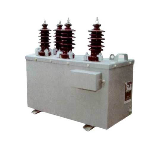
The SZW-10K is a single-phase, indoor-type, cast-resin insulated voltage transformer (VT) engineered for precise voltage measurement and reliable protective relay operation in 11kV (IEC-rated) / 10kV (domestic system) medium-voltage networks. Designed in strict accordance with IEC 61869-3 and GB/T 20840.3, this instrument transformer delivers high accuracy under both steady-state and transient conditions while providing essential galvanic isolation between primary and secondary circuits.
Operating Principle of Cast-Resin Insulation
Cast-resin insulation in the SZW-10K employs vacuum pressure impregnation (VPI) technology using cycloaliphatic epoxy resin systems. This process fully encapsulates the primary and secondary windings along with the GOES (grain-oriented electrical steel) core, eliminating air voids that could lead to partial discharges. The resin matrix provides superior dielectric strength—typically exceeding 20 kV/mm—and excellent tracking resistance (CTI > 600). Unlike oil-filled units, the solid insulation is non-flammable, requires no maintenance for fluid levels or gas monitoring, and exhibits minimal aging under thermal cycling from –25°C to +40°C ambient conditions. The homogeneous structure also ensures consistent thermal conductivity (~0.8 W/m·K), enabling efficient heat dissipation during continuous operation at rated burden.
Advantages Over Oil-Immersed Designs
Compared to traditional oil-immersed VTs, the SZW-10K eliminates fire hazards, environmental contamination risks, and complex sealing requirements. Its compact footprint—approximately 30% smaller than equivalent oil units—facilitates integration into space-constrained switchgear such as RMUs and metal-clad panels. The absence of liquid insulation removes concerns about moisture ingress, oil degradation, or pressure relief mechanisms. Furthermore, cast-resin construction offers higher mechanical rigidity, reducing susceptibility to vibration-induced winding displacement during short-circuit events. Partial discharge levels are maintained below 10 pC at 1.2 × Um/√3 (where Um = 12 kV), ensuring long-term reliability per IEC 60270.
Typical Applications Overview
The SZW-10K is deployed across utility substations, industrial plants, commercial complexes, and renewable energy interconnection points where accurate voltage sensing is critical. Primary applications include revenue metering (accuracy class 0.2 or 0.5), overvoltage/undervoltage protection relaying (class 3P or 6P), and synchro-check functions in generator synchronization schemes. Its robust design supports operation in polluted environments (up to pollution degree III per IEC 60664-1) and altitudes up to 1,000 meters without derating. The transformer’s low thermal time constant (< 30 minutes) enables rapid response to load transients, making it suitable for dynamic grid monitoring in smart distribution systems.
Technical Specifications
The SZW-10K is engineered to deliver consistent performance under defined electrical and environmental parameters. All specifications comply with IEC 61869-3:2011 and GB/T 20840.3-2017.
| Parameter | Value |
|---|---|
| Primary Voltage (Up) | 11,000 V (IEC) / 10,000 V (Domestic) |
| Secondary Voltage (Us) | 100 V or 100/√3 V (standard); optional 110 V |
| Voltage Ratio | 11,000/100 V; 11,000/100/√3 V |
| Accuracy Classes | Metering: 0.2, 0.5; Protection: 3P, 6P |
| Rated Output (per secondary) | 10–100 VA (configurable) |
| Insulation Level (LI/AC) | 75 kV / 28 kV (1 min, 50 Hz) |
| Short-Time Thermal Current | 100 × In for 1 s (secondary short-circuited) |
| Core Material | GOES silicon steel, 0.27 mm thickness |
| Resin System | Cycloaliphatic epoxy, VPI process |
| Ambient Temperature Range | –25°C to +40°C |
| Relative Humidity | ≤ 95% (non-condensing) |
| Altitude Limit | ≤ 1,000 m (derating required above) |
Rated Voltage and Ratio Configuration
The SZW-10K is rated for a highest voltage for equipment (Um) of 12 kV, corresponding to an IEC system voltage of 11 kV. Domestic installations operating at nominal 10 kV utilize the same physical unit due to standardized insulation coordination. Standard secondary voltages are 100 V (for phase-to-phase measurements) or 100/√3 V (for phase-to-ground in wye-connected systems). Custom ratios such as 11,000/110 V are available upon request but require verification of burden compatibility. The turns ratio tolerance is ±0.25% for metering classes and ±1.0% for protection classes, ensuring compliance with IEC 61869-3 clause 5.3.2.
Service Conditions and Environmental Limits
Designed for indoor installation only, the SZW-10K operates reliably within ambient temperatures from –25°C to +40°C. At temperatures below –5°C, pre-heating may be required if condensation is present on the housing prior to energization. Relative humidity must not exceed 95% without condensation, as prolonged exposure to moisture can degrade surface resistivity. For installations above 1,000 m altitude, the power frequency withstand voltage must be reduced by 1% per 100 m increment above sea level per IEC 60071-2. The transformer is not rated for outdoor use due to UV sensitivity of the epoxy resin and lack of IP-rated enclosure (typical IP00).
Typical Applications
The SZW-10K serves diverse roles in modern power systems where precision, safety, and longevity are paramount.
Substation Secondary Metering
In 10/11kV distribution substations, the SZW-10K provides isolated, scaled-down voltage signals to revenue-class energy meters (e.g., IEC 62053-22 compliant). With accuracy class 0.2, it ensures billing errors remain below ±0.2% across 80–120% of rated voltage and 25–100% of rated burden. The low phase displacement (< 10 minutes for class 0.2) minimizes reactive energy measurement errors. Integration with digital metering systems via RS-485 or Modbus RTU is common, requiring stable secondary output unaffected by harmonic distortion up to the 13th order.
Industrial Power Distribution
Within manufacturing facilities, the SZW-10K feeds voltage inputs to multifunction protection relays (e.g., overvoltage ANSI 59, undervoltage ANSI 27). Its 3P or 6P accuracy class guarantees correct operation during fault conditions—maintaining error within ±3% or ±6% respectively at 5% to 100% of rated voltage. In arc flash mitigation schemes, fast-acting undervoltage elements rely on the VT’s linear response down to 10% of nominal voltage. The compact size allows mounting directly in motor control centers (MCCs) or switchboards without external cubicles.
Renewable Energy Integration
Solar PV and wind farms connecting at 10kV utilize the SZW-10K for grid synchronization and anti-islanding protection. During islanding events, voltage deviations as small as ±5% must be detected within 200 ms—requiring low output impedance and minimal transient overshoot. The VT’s high saturation margin (> 1.9 × Un) prevents core saturation during voltage swells caused by sudden load rejection. Additionally, its immunity to DC offset (common in inverter-based resources) ensures stable operation without remanence-induced errors.
Rural and Suburban Distribution Networks
In remote feeders with long cable runs, the SZW-10K supports voltage regulation via automatic tap changers (ATCs) and capacitor bank controllers. Its consistent ratio stability over temperature (±0.05%/°C) compensates for line drop variations. For pole-mounted or pad-mounted transformers serving residential clusters, the VT enables remote voltage monitoring through SCADA systems, facilitating proactive voltage correction before customer complaints arise. The 25-year design life reduces replacement frequency in hard-to-access locations.
Compliance with International Standards
The SZW-10K is certified to IEC 61869-3:2011 (“Instrument transformers – Part 3: Additional requirements for inductive voltage transformers”) and aligns with China’s GB/T 20840.3-2017, which adopts IEC 61869-3 with minor national deviations.
IEC 61869-3 Compliance Details
Key IEC 61869-3 requirements met include: rated insulation levels (LI 75 kV, AC 28 kV), temperature rise limits (≤ 55 K for resin, ≤ 60 K for windings), and accuracy performance under composite error conditions. The standard mandates that protection-class VTs maintain specified error limits at voltages up to 1.9 × Un for 30 seconds—verified during type testing. Partial discharge measurements are conducted at 1.2 × Um/√3 with acceptance criteria of ≤ 10 pC. Additionally, the SZW-10K undergoes impulse testing with 1.2/50 µs waves at ±75 kV, with no disruptive discharge permitted.
GB/T 20840.3 Alignment and National Variations
GB/T 20840.3 mirrors IEC 61869-3 but includes supplementary requirements for Chinese grid conditions. Notably, GB specifies a minimum short-circuit withstand capability of 100 × In for 1 second (vs. IEC’s functional requirement without fixed value). Domestic standards also mandate stricter labeling in Mandarin and inclusion of a secondary shorting link for safety during maintenance. While IEC permits accuracy verification at 20%, 50%, 80%, 100%, and 120% of rated voltage, GB requires additional testing at 5% for protection classes—a condition the SZW-10K satisfies with error < 8% for 6P class.
Testing and Certification Protocols
Type tests per IEC 61869-3 include temperature rise, short-circuit, impulse, and accuracy verification under varying burden and frequency (45–55 Hz). Routine tests performed on every unit include power frequency withstand (28 kV, 1 min), turns ratio (±0.25% tolerance), polarity, and insulation resistance (> 1,000 MΩ at 2,500 V DC). Third-party certification from CQC (China Quality Certification) and SGS confirms compliance.
On-Site Testing Procedures
Post-installation verification ensures the SZW-10K performs within specification before commissioning.
Insulation Resistance Test
Using a 2,500 V DC megohmmeter, measure insulation resistance between primary winding and ground, secondary winding and ground, and primary-to-secondary. Acceptance criterion: ≥ 1,000 MΩ at 20°C. Correct for temperature using RT = R20 × 1.5(20–T)/10. Values below 500 MΩ indicate moisture ingress or resin cracking and require investigation. Perform before and after power frequency withstand testing to detect insulation degradation.
Turns Ratio Test
Apply a low-voltage AC source (50–200 V) to the primary and measure secondary voltage with a calibrated voltmeter (accuracy class 0.1). Calculate actual ratio and compare to nameplate. Tolerance: ±0.25% for metering, ±1.0% for protection. Example: For 11,000/100 V ratio, measured secondary at 110 V primary should be 1.000 V ± 0.0025 V (metering). Use a dedicated ratio tester (e.g., Omicron CT Analyzer) for automated comparison and phase angle measurement.
Polarity Test
Verify reducing polarity using the DC kick method: momentarily connect a 6–12 V battery across primary terminals (H1+, H2–). Observe secondary voltage polarity with a DC voltmeter—positive deflection at X1 indicates correct reducing polarity. Incorrect polarity causes 180° phase shift, leading to metering errors and relay misoperation. Polarity must match adjacent CTs in three-phase systems for proper vector summation.
Power Frequency Withstand Voltage Test
Apply 28 kV RMS at 50 Hz between primary and grounded secondary/core for 1 minute. Use a calibrated test transformer with overcurrent protection set at 10 mA. No flashover or sustained arcing is permitted. Reduce voltage gradually post-test to avoid transient overvoltages. This test validates insulation integrity after transportation and installation stresses. Do not perform if ambient humidity exceeds 80%.
Open-Circuit Characteristic Test
With secondary open, apply increasing primary voltage from 20% to 120% of Un and record excitation current. Plot V-I curve to verify no abnormal saturation below 1.5 × Un. At 100% voltage, excitation current should be < 0.5% of rated secondary current. A sharp current rise indicates core defects or shorted turns. This test is critical for detecting manufacturing flaws missed in routine tests.
Preventive Maintenance Guide
Although cast-resin VTs require minimal maintenance, periodic checks extend service life beyond 25 years.
Annual Visual and Electrical Inspection
Inspect for surface tracking, cracks, or discoloration on the resin housing. Clean with dry cloth—never use solvents. Check terminal tightness (torque: 12 N·m for M6 studs). Measure insulation resistance annually; a 30% drop from baseline warrants further diagnostics. Verify secondary wiring integrity and grounding continuity (< 0.1 Ω resistance). Ensure secondary circuits are never left open during operation to prevent dangerous overvoltages.
Five-Year Comprehensive Assessment
Every five years, perform partial discharge measurement using IEC 60270 methods. Acceptable level: ≤ 15 pC at 1.2 × Um/√3. Conduct thermal imaging under load to detect hot spots (> 10 K above ambient indicates internal fault). Re-calibrate accuracy if used for revenue metering—drift beyond ±0.1% for class 0.2 requires replacement. Update maintenance logs with test results for lifecycle tracking.
Maintenance Intervals and Fault Diagnosis
| Interval | Action | Fault Indicator |
|---|---|---|
| Annually | Visual inspection, IR test | Cracks, tracking, IR < 500 MΩ |
| 3 Years | Terminal torque check | Loose connections, overheating |
| 5 Years | PD test, accuracy verification | PD > 15 pC, ratio error > tolerance |
| As Needed | Thermal scan under load | Hot spot > 70°C |
Common faults include secondary winding opens (causing infinite IR), core lamination shorts (elevated excitation current), and terminal corrosion (increased contact resistance). Replace unit if internal damage is suspected—field repair of cast-resin units is not feasible.
Conclusion
The SZW-10K 11kV cast-resin voltage transformer represents a benchmark in reliability, accuracy, and safety for medium-voltage applications. Its VPI epoxy resin insulation eliminates fire and environmental risks associated with oil-filled alternatives, while the GOES silicon steel core ensures low losses and high linearity across the operational range. Certified to IEC 61869-3 and GB/T 20840.3, the SZW-10K meets stringent global requirements for both metering (class 0.2/0.5) and protection (3P/6P) duties. With a design life exceeding 25–30 years under normal service conditions, it offers exceptional total cost of ownership through zero fluid maintenance, compact installation footprint, and resilience to pollution and humidity. Field-proven in utility substations, industrial plants, and renewable integration projects worldwide, the SZW-10K delivers consistent performance even under transient overvoltages and harmonic distortion. Its rigorous factory and site testing protocols guarantee compliance from commissioning through decades of service, making it a trusted choice for engineers prioritizing grid accuracy, personnel safety, and long-term asset reliability in 10/11kV networks.
Frequently Asked Questions (FAQ)
Q1: Can the SZW-10K be used outdoors?
No. The SZW-10K is rated for indoor use only (IP00). Outdoor exposure to UV radiation degrades epoxy resin, and lack of weatherproofing risks moisture ingress.
Q2: What is the maximum altitude for installation without derating?
1,000 meters above sea level. Above this, reduce power frequency withstand voltage by 1% per 100 m increment per IEC 60071-2.
Q3: Is secondary shorting required during maintenance?
Yes. Always short-circuit secondary terminals before disconnecting loads to prevent dangerous overvoltages from capacitive coupling.
Q4: Can multiple burdens be connected to one secondary winding?
Only if the total VA does not exceed the rated output (e.g., 30 VA max for a 30 VA winding). Exceeding burden increases ratio and phase errors beyond accuracy class limits.
Q5: How often should accuracy be re-verified for revenue metering?
Every 5 years per most utility standards, or after any event causing mechanical shock (e.g., nearby short circuit).
Q6: What causes high excitation current in open-circuit tests?
Core lamination shorts, winding-to-core faults, or excessive remanence. Values > 0.5% of rated secondary current indicate internal defects.
Q7: Is the SZW-10K compatible with digital relays?
Yes. Its low output impedance and linear response support modern numerical relays requiring stable voltage input under distorted waveforms.
Q8: What torque should be used on primary terminals?
12 N·m for M6 studs. Under-torquing causes overheating; over-torquing risks thread stripping or resin cracking.