Article Content
Introduction
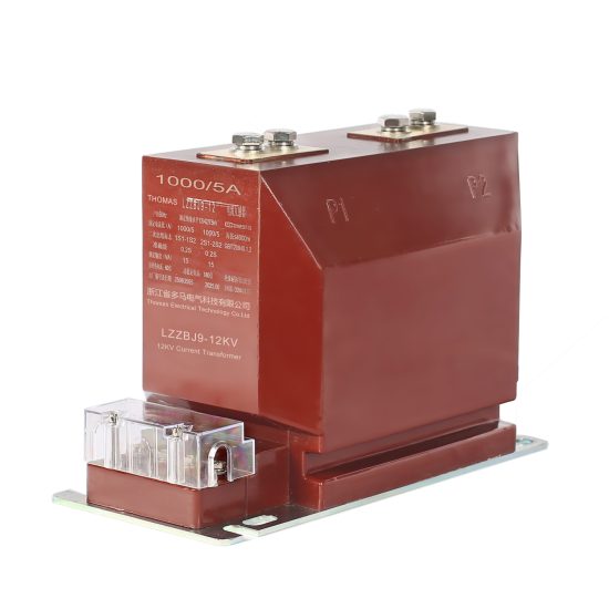
The LZZBJ9-10 current transformer is a resin-insulated, indoor-type instrument transformer designed for accurate current measurement and protection in 10kV power systems. It conforms to international standards such as IEC 61869 and GB/T 20840, ensuring high reliability, thermal stability, and long service life under normal operating conditions. This device plays a critical role in monitoring electrical parameters, enabling protective relaying, and facilitating energy metering within medium-voltage switchgear installations.
Proper testing and maintenance of the LZZBJ9-10 are essential to guarantee operational safety, measurement accuracy, and compliance with grid regulations. Over time, environmental factors (e.g., humidity, dust, thermal cycling), mechanical stress, or insulation degradation may affect performance. Therefore, a structured approach to commissioning and periodic maintenance is required to detect early signs of deterioration and prevent catastrophic failures such as insulation breakdown or inaccurate current transformation.
This manual provides detailed procedures for initial commissioning tests after installation and routine maintenance activities throughout the transformer’s service life. It is intended for use by qualified electrical engineers, field technicians, and maintenance personnel who possess appropriate training in high-voltage equipment handling and safety protocols. All work must be performed in accordance with local electrical codes, utility guidelines, and manufacturer specifications. Adherence to these procedures ensures optimal performance, extends equipment lifespan, and supports the integrity of the entire power distribution system.
Commissioning Tests
Commissioning tests for the LZZBJ9-10 current transformer must be conducted after installation but before energizing the primary circuit. These tests verify correct installation, insulation integrity, winding continuity, polarity, and transformation accuracy. All tests should be performed using calibrated instruments and documented in a test report for future reference.
2.1 Visual and Mechanical Inspection
Before any electrical testing, conduct a thorough visual inspection:
- Check for physical damage to the resin housing, terminal blocks, or mounting hardware.
- Ensure nameplate data (ratio, accuracy class, burden, etc.) matches design specifications.
- Verify that all secondary terminals are clean, tight, and correctly labeled (e.g., S1, S2).
- Confirm that the transformer is securely mounted and properly grounded via the grounding lug.
2.2 Insulation Resistance Test
Measure insulation resistance between windings and ground using a 2500 V DC megohmmeter. The test duration is 1 minute. Acceptable values are typically ≥1000 MΩ at 20°C. Correct for temperature if necessary using standard correction factors.
| Test Point | Test Voltage (DC) | Minimum Acceptable Value | Notes |
|---|---|---|---|
| Primary to Ground | 2500 V | ≥1000 MΩ | Secondary terminals shorted and grounded |
| Secondary to Ground | 500 V | ≥100 MΩ | Primary open-circuited |
| Primary to Secondary | 2500 V | ≥1000 MΩ | Ground isolated |
2.3 Winding Continuity and Polarity Check
Use a low-resistance ohmmeter to confirm continuity of both primary and secondary windings. Record resistance values for baseline comparison. Then, verify polarity using the DC kick method or a dedicated polarity tester. For the LZZBJ9-10, standard polarity is subtractive: when current enters P1 on the primary, it exits S1 on the secondary.
2.4 Turns Ratio and Accuracy Verification
Perform a turns ratio test using a dedicated CT analyzer (e.g., Omicron CPC 100 or equivalent). Inject a known primary current (typically 10–100% of rated current) and measure secondary output. The measured ratio should be within ±0.5% of the nominal ratio for metering cores (e.g., 0.5 class) and within ±1% for protection cores (e.g., 5P10).
| Core Type | Nominal Ratio | Test Current (% of In) | Max Ratio Error | Phase Displacement Limit |
|---|---|---|---|---|
| Metering (0.5) | e.g., 400/5 | 10%, 50%, 100% | ±0.5% | ≤30 minutes |
| Protection (5P10) | e.g., 400/5 | 100%, 1000% (if applicable) | ±1.0% | Not specified (accuracy focus) |
2.5 Secondary Burden and Excitation Test
Measure the actual burden connected to each secondary winding and ensure it does not exceed the rated burden (e.g., 15 VA, 30 VA). Additionally, perform an excitation (saturation) test on protection windings: gradually increase voltage across the secondary winding while measuring current. The knee-point voltage should align with manufacturer data (typically 300–500 V for 5P10 cores). A significant deviation indicates core issues or incorrect winding configuration.
Routine Maintenance
Routine maintenance of the LZZBJ9-10 current transformer is critical to sustaining long-term reliability and measurement fidelity. While this resin-cast CT is largely maintenance-free due to its solid insulation, periodic inspections and tests help identify latent defects before they escalate into failures. Maintenance frequency depends on operating environment, load profile, and utility policy—typically every 3 to 5 years for indoor installations.
3.1 Visual and Environmental Inspection
Inspect the transformer during scheduled outages:
- Examine the resin body for cracks, tracking, discoloration, or surface contamination.
- Check terminal connections for corrosion, overheating marks (discoloration), or looseness.
- Ensure no foreign objects or moisture accumulation near terminals or base.
- Verify grounding continuity from the transformer frame to the switchgear ground bus.
3.2 Insulation Resistance Re-test
Repeat the insulation resistance test as performed during commissioning. Compare results with baseline values. A reduction of more than 50% may indicate moisture ingress or insulation aging and warrants further investigation.
| Maintenance Interval | Test Performed | Acceptance Criteria | Action if Failed |
|---|---|---|---|
| Every 3–5 years | Insulation Resistance (Primary-Ground) | ≥500 MΩ (minimum); ≥80% of baseline preferred | Clean surface; retest dry. If still low, consider replacement. |
| Every outage | Terminal Tightness & Visual Condition | No corrosion, overheating, or looseness | Clean and retorque to 12–15 N·m (as per spec) |
| After fault event | Excitation Curve & Ratio Test | Within ±1% of original curve | If distorted, replace CT |
3.3 Secondary Circuit Integrity
Ensure secondary circuits remain closed during all maintenance activities—never leave CT secondaries open-circuited while the primary is energized or could be energized. Verify that shorting links or test switches function correctly. Measure loop resistance of secondary wiring to confirm burden remains within rated limits.
3.4 Record Keeping
Maintain a logbook or digital record for each LZZBJ9-10 unit, including:
- Installation date and location
- Commissioning test results
- All maintenance dates and findings
- Any anomalies or corrective actions
Trend analysis of insulation resistance and excitation data over time provides early warning of degradation and supports predictive maintenance strategies.
4. Periodic Testing
Periodic testing is a scheduled, systematic evaluation of electrical systems and equipment to ensure continued safety, reliability, and compliance with regulatory standards. Conducted at predetermined intervals—such as annually, semi-annually, or quarterly—these tests help identify degradation, wear, or latent faults before they lead to failure or hazardous conditions. The frequency of testing depends on equipment type, operating environment, manufacturer recommendations, and applicable codes (e.g., NFPA 70B, IEEE standards).
Key components subject to periodic testing include transformers, switchgear, circuit breakers, protective relays, grounding systems, and insulation resistance of cables and windings. Common test methods include insulation resistance (IR) testing, polarization index (PI) measurement, dielectric absorption ratio (DAR), power factor/dissipation factor testing, and thermal imaging.
| Test Type | Typical Interval | Purpose | Acceptance Criteria |
|---|---|---|---|
| Insulation Resistance (IR) | Annually | Evaluate integrity of insulation in motors, cables, and transformers | IR ≥ 1 MΩ per 1,000 V rating; trend-based comparison preferred |
| Circuit Breaker Mechanical Operation | Every 3–5 years | Verify proper opening/closing timing and contact alignment | Within manufacturer’s time tolerance (±10 ms typical) |
| Protective Relay Calibration | Every 2–5 years | Ensure accurate trip settings and response times | Operation within ±5% of setpoint |
| Ground Resistance Test | Annually or after soil disturbance | Confirm low-impedance path to earth | ≤5 Ω for critical systems; ≤25 Ω acceptable in some cases |
| Thermal Imaging Scan | Semi-annually (under load) | Detect abnormal heating due to loose connections or overloads | ΔT ≤ 15°C above ambient or similar-phase component |
Periodic testing must be documented thoroughly, with baseline readings established during commissioning to enable meaningful trend analysis. Deviations from historical data—even if within absolute limits—may indicate emerging issues requiring investigation. All personnel performing these tests must be qualified and use calibrated instruments compliant with IEC 61010 safety standards.
5. Diagnostic Testing
Diagnostic testing goes beyond routine verification to investigate specific anomalies, performance deviations, or suspected failures within electrical systems. Unlike periodic testing, which follows a fixed schedule, diagnostic testing is condition-driven and often initiated in response to alarms, unexpected shutdowns, thermal hotspots, or abnormal operational behavior.
This form of testing employs advanced techniques to pinpoint root causes, such as partial discharge (PD) analysis in medium- and high-voltage equipment, oil dissolved gas analysis (DGA) for transformers, or vibration analysis for rotating machinery. Diagnostic tools may include oscilloscopes, power quality analyzers, ultrasonic detectors, and specialized software for waveform capture and harmonic distortion assessment.
| Diagnostic Method | Application | Indicators of Fault |
|---|---|---|
| Partial Discharge (PD) Testing | Cables, switchgear, transformers | Repetitive high-frequency pulses indicating insulation voids or tracking |
| Dissolved Gas Analysis (DGA) | Oil-filled transformers | Elevated levels of hydrogen, acetylene, or methane signaling thermal/electrical faults |
| Power Quality Logging | Entire distribution system | Voltage sags, swells, harmonics >5%, flicker, or unbalance >3% |
| Motor Current Signature Analysis (MCSA) | Induction motors | Sidebands around fundamental frequency indicating rotor bar or bearing defects |
Effective diagnostic testing requires not only technical expertise but also access to historical performance data for comparative analysis. Findings should lead directly to corrective actions or further targeted inspections, minimizing downtime and preventing catastrophic failure.
6. Troubleshooting
Troubleshooting is the systematic process of identifying, isolating, and resolving electrical faults that disrupt normal system operation. It combines logical reasoning, knowledge of system design, and practical measurement techniques to restore functionality safely and efficiently. Successful troubleshooting relies on a structured approach rather than random part replacement or guesswork.
The standard methodology includes: (1) verifying the problem through observation and operator interviews, (2) reviewing schematics and recent maintenance records, (3) performing non-invasive checks (e.g., visual inspection, thermal scan), (4) taking voltage, current, and continuity measurements under de-energized or energized conditions as appropriate, and (5) isolating the faulty component through segmentation or substitution.
Common electrical faults include open circuits, short circuits, ground faults, control logic errors, relay miscoordination, and sensor malfunctions. Safety is paramount—technicians must follow lockout/tagout (LOTO) procedures per OSHA 29 CFR 1910.147 and use PPE rated for the arc flash hazard level.
| Symptom | Potential Causes | Troubleshooting Steps |
|---|---|---|
| Motor fails to start | Blown fuse, open contactor coil, faulty overload relay, broken wire | Check supply voltage → inspect control circuit → test continuity of coil and contacts → verify overload reset |
| Nuisance tripping of breaker | Overload, short circuit, ground fault, harmonic resonance, or defective breaker | Measure load current → inspect for insulation damage → perform ground fault test → analyze harmonics → test breaker calibration |
| Intermittent PLC output | Loose terminal, failing output module, EMI interference, programming error | Inspect wiring torque → monitor output with oscilloscope → check grounding/shielding → validate ladder logic |
| Unstable voltage at panel | Loose neutral, overloaded phase, utility-side fluctuation, transformer tap issue | Measure phase-to-neutral voltages → inspect neutral connections → log voltage over time → coordinate with utility |
Documentation during troubleshooting is essential—not only for resolving the immediate issue but also for future reference. A well-maintained log of symptoms, measurements, and corrective actions accelerates diagnosis during recurring problems and supports continuous improvement in system reliability.
7. Record Keeping
Accurate and comprehensive record keeping is a cornerstone of effective electrical maintenance programs. Maintenance logs, test reports, calibration certificates, and repair histories provide traceability, support compliance audits, and enable predictive analytics. Records should be retained for the life of the equipment plus a minimum of seven years, as recommended by NFPA 70B and many insurance providers.
Essential documentation includes: equipment nameplate data, as-built drawings, commissioning reports, periodic test results with timestamps and technician IDs, calibration records for test instruments, material safety data sheets (MSDS) for insulating fluids, and incident reports for any electrical failures or near-misses.
| Record Type | Retention Period | Key Information Included |
|---|---|---|
| Test Reports | Life of equipment + 7 years | Date, equipment ID, test parameters, results, pass/fail status, technician signature |
| Calibration Logs | Until next calibration + 5 years | Instrument ID, calibration date, standards used, correction factors, certificate number |
| Maintenance Work Orders | Life of equipment + 7 years | Description of work, parts replaced, labor hours, before/after photos, supervisor approval |
| Arc Flash Risk Assessments | Updated every 5 years or after major changes | Incident energy levels, PPE requirements, boundary distances, system configuration |
Digital asset management systems (CMMS) are strongly encouraged to streamline record storage, retrieval, and trend analysis. All records must be protected from unauthorized alteration and backed up regularly to prevent data loss.
8. Maintenance Planning
Maintenance planning ensures that all testing, inspection, and repair activities are executed efficiently, safely, and with minimal disruption to operations. A well-developed plan aligns maintenance tasks with production schedules, resource availability, and risk priorities. It begins with a thorough inventory of electrical assets and their criticality rankings (e.g., using a Failure Modes and Effects Analysis—FMEA).
The plan should define task frequencies, required skill sets, necessary tools and spare parts, estimated durations, and safety protocols. Integration with a Computerized Maintenance Management System (CMMS) enables automated work order generation, preventive maintenance scheduling, and performance tracking against KPIs such as mean time between failures (MTBF) and schedule compliance rate.
| Planning Element | Description |
|---|---|
| Asset Criticality Assessment | Ranks equipment based on impact of failure (safety, production, cost) |
| Task Standardization | Develops step-by-step job plans with safety checks and quality criteria |
| Resource Allocation | Schedules personnel, tools, and materials in advance to avoid delays |
| Outage Coordination | Aligns maintenance windows with production downtime to minimize losses |
Regular review and continuous improvement of the maintenance plan—based on actual performance data, root cause analyses, and changes in operational demands—are essential to sustain system reliability and optimize lifecycle costs.