Article Content
IEC 61869-2 Certified 11kV Cast-Resin Current Transformer LFS-10 for Metering & Protection Applications
Introduction to the LFS-10 Current Transformer
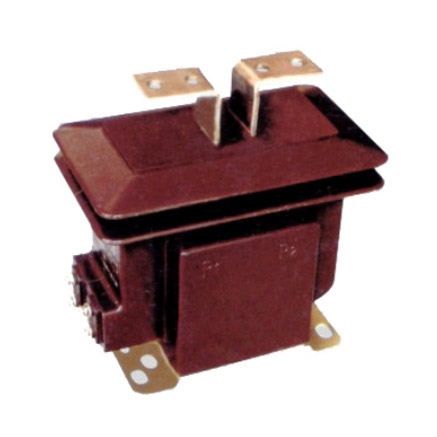
The LFS-10 is a medium-voltage cast-resin current transformer engineered for precision current measurement and protective relaying in 11kV (IEC) / 10kV (domestic) electrical networks. Designed for both indoor and outdoor deployment, this instrument leverages vacuum pressure impregnation (VPI) epoxy resin technology to deliver superior dielectric strength, environmental resilience, and long-term stability. Unlike traditional oil-immersed CTs, the LFS-10 eliminates fire hazards, oil leakage risks, and maintenance-intensive sealing systems, making it ideal for urban substations, renewable energy interconnections, and remote distribution infrastructure.
Operating Principle of Cast-Resin Insulation
Cast-resin insulation in the LFS-10 utilizes a two-component cycloaliphatic epoxy system cured under vacuum and pressure to fully encapsulate the primary conductor and secondary windings. This process eliminates air voids and moisture ingress pathways, achieving a homogeneous dielectric structure with a relative permittivity (εr) of approximately 4.2 and volume resistivity exceeding 1×10¹⁴ Ω·cm at 20°C. The VPI technique ensures complete impregnation of the GOES (grain-oriented electrical steel) core laminations, minimizing partial discharge activity to below 5 pC at 1.2 × Um/√3 (where Um = 12 kV). This results in exceptional thermal conductivity (0.8–1.2 W/m·K), enabling efficient heat dissipation during continuous operation or short-circuit events.
Advantages Over Oil-Immersed Designs
Compared to oil-filled CTs, the LFS-10 offers significant operational and safety benefits. Its solid insulation system is non-flammable (UL 94 V-0 rated), eliminating explosion risks in confined spaces. The absence of gaskets, conservators, and oil expansion tanks reduces mechanical failure points and extends mean time between failures (MTBF) to over 30 years. Additionally, cast-resin CTs exhibit lower temperature rise—typically ≤55 K above ambient under rated load per IEC 61869-2—due to direct thermal coupling between windings and the external housing. Environmental compliance is enhanced as the unit contains no PCBs or hydrocarbons, satisfying RoHS and REACH directives. Weight is reduced by 30–40% versus equivalent oil units, simplifying handling and mounting on pole-top or pad-mounted switchgear.
Typical Application Overview
The LFS-10 serves dual roles in power systems: revenue-grade metering (accuracy classes 0.2S or 0.5S) and protective relaying (classes 5P10 or 5P20). It is commonly deployed in 11kV ring main units (RMUs), secondary substations feeding commercial complexes, and grid-connected solar farms where harmonic distortion from inverters demands high linearity. In rural electrification projects, its IP54-rated enclosure withstands dust, humidity, and temperature swings from –40°C to +55°C. The transformer’s compact footprint (typical dimensions: 280 mm height × 180 mm diameter) allows retrofitting into legacy switchgear without structural modifications.
Technical Specifications
The LFS-10 adheres strictly to IEC 61869-2 and GB/T 20840.2, with key parameters validated through type, routine, and special tests per standard requirements.
| Parameter | Value |
|---|---|
| Rated Voltage (Ur) | 11 kV (IEC) / 10 kV (domestic) |
| Maximum System Voltage (Um) | 12 kV |
| Primary Current (Ip) | 50 A to 3000 A (standard ratios) |
| Secondary Current (Is) | 1 A or 5 A |
| Accuracy Class (Metering) | 0.2S, 0.5S |
| Accuracy Class (Protection) | 5P10, 5P20 |
| Rated Burden | 2.5 VA to 30 VA (per class) |
| Short-Time Thermal Current (Ith) | 20 kA for 1 s (or 40 kA for 0.5 s) |
| Dynamic Withstand Current | 50 kA peak |
| Insulation Level (LI/AC) | 75 kV / 28 kV (1 min) |
| Partial Discharge | <5 pC at 1.2 × Um/√3 |
| Ambient Temperature Range | –40°C to +55°C |
| Altitude Limit | ≤1000 m (derating required above) |
| Humidity | Up to 100% RH, condensing |
Standard Service Conditions
The LFS-10 is rated for normal service conditions per IEC 61869-2 Clause 4.1: ambient temperature from –40°C to +55°C, relative humidity up to 100% (including condensation), and installation altitude not exceeding 1000 m above sea level. At altitudes between 1000 m and 2000 m, the power frequency withstand voltage must be reduced by 1% per 100 m increment. The unit is designed for continuous operation under unbalanced three-phase loads and can tolerate harmonic currents up to the 13th order without exceeding accuracy limits, provided total harmonic distortion (THD) remains below 15%. Installation inclination is permitted up to ±5° from vertical without affecting performance.
Core and Winding Configuration
The magnetic circuit employs high-permeability GOES laminations (M4 grade, 0.3 mm thickness) with a core cross-section optimized for low excitation current (<0.5% of rated secondary current at 100% burden). Secondary windings are wound with electrolytic-tough-pitch (ETP) copper wire (Class F insulation, 155°C rating) and embedded in the resin matrix to prevent movement under electromagnetic forces. Multi-ratio models feature tapped windings accessible via terminal blocks rated for 600 V, allowing field reconfiguration without disassembly. The primary conductor is a solid aluminum or copper busbar with bolted connections rated for 125 A/mm² current density.
Typical Applications
The LFS-10’s dual-certification for metering and protection enables versatile deployment across modern power infrastructure.
Substation Secondary Metering
In 11kV/400V urban substations, the LFS-10 provides revenue-grade current signals to smart meters compliant with DLMS/COSEM protocols. Installed on the HV side of distribution transformers, it operates under 0.2S accuracy class with a 5 VA burden, ensuring billing accuracy within ±0.2% from 1% to 120% of rated current. Its high linearity minimizes errors during light-load periods (e.g., nighttime residential demand), critical for time-of-use tariff structures. The cast-resin housing resists tracking from pollution in coastal or industrial zones, maintaining insulation integrity over decades.
Industrial Power Distribution
Within manufacturing plants, the LFS-10 feeds data to power quality analyzers and motor protection relays. For example, on a 11kV feeder supplying induction furnaces, the CT’s 5P20 class ensures relay operation remains reliable even during severe voltage sags that cause current surges up to 20× rated. The unit’s robust mechanical design withstands vibrations from nearby heavy machinery, while its flame-retardant resin meets IEC 60695 glow-wire test requirements (GWFI 850°C).
Renewable Energy Integration
Solar photovoltaic (PV) farms require CTs that maintain accuracy despite DC offset and high-frequency harmonics from inverters. The LFS-10’s GOES core exhibits low hysteresis loss (<1.2 W/kg at 1.5 T, 50 Hz), reducing remanence after fault clearance. In a typical 10 MW solar plant, multiple LFS-10 units monitor export feeders to the grid, interfacing with SCADA systems via IEC 61850-9-2 LE sampled values. The outdoor-rated enclosure (UV-stabilized resin) prevents degradation under prolonged solar exposure.
Rural and Suburban Distribution Networks
In remote areas with limited maintenance access, the LFS-10’s sealed construction eliminates oil top-up needs. Mounted on pole-top reclosers, it enables automated sectionalizing during faults. For instance, in a 11kV overhead line serving agricultural communities, the CT’s 5P10 class triggers recloser tripping within 30 ms of a phase-to-ground fault, minimizing outage duration. Its lightweight design (≈18 kg) facilitates installation using standard bucket trucks.
Compliance with International Standards
The LFS-10 is certified to IEC 61869-2:2012 (Instrument transformers – Part 2: Additional requirements for current transformers) and aligns with China’s GB/T 20840.2-2014, ensuring global interoperability.
IEC 61869-2 Compliance Details
Key IEC 61869-2 requirements met include: composite error ≤10% for 5P class at specified ALF (accuracy limit factor); temperature rise ≤55 K for windings; power frequency withstand voltage of 28 kV for 1 minute; and lightning impulse withstand of 75 kV (1.2/50 μs wave). The standard mandates that metering CTs maintain composite error within ±0.2% (class 0.2S) from 1% to 120% of rated current, verified through calibrated burden boxes and precision ammeters. Type tests include temperature cycling (–40°C to +70°C, 10 cycles) and seismic testing (0.3g horizontal acceleration).
GB/T 20840.2 Alignment
While GB/T 20840.2 closely mirrors IEC 61869-2, it imposes stricter partial discharge limits (<3 pC at 1.2 × Um/√3) and requires additional salt fog testing (1000 hours per IEC 60068-2-11) for coastal applications. The LFS-10 exceeds these via enhanced resin formulation with nano-alumina fillers that suppress ionization. Domestic certification also mandates short-circuit testing at 1.1 × Ith to validate mechanical robustness—a requirement absent in IEC but critical for Chinese utility grids with high fault levels.
Key Differences Between IEC and Domestic Standards
The primary divergence lies in environmental testing: GB/T 20840.2 includes sand-dust ingress testing (IP6X) and higher UV resistance thresholds, reflecting China’s arid western regions. IEC focuses more on electromagnetic compatibility (EMC) for digital output CTs, though the LFS-10’s analog output avoids this complexity. Both standards agree on core performance metrics, but GB/T uses “rated symmetrical short-circuit current factor” instead of “ALF,” requiring documentation conversion for export markets. All LFS-10 units undergo dual-certification testing at accredited labs (e.g., KEMA, CESI, and China Electric Power Research Institute).
On-Site Testing Procedures
Post-installation verification ensures the LFS-10 performs within specification before energization.
Insulation Resistance Test
Using a 2500 V DC megohmmeter, measure insulation resistance between primary-to-secondary, primary-to-ground, and secondary-to-ground. Acceptance criteria: ≥1000 MΩ at 20°C. Correct for temperature using RT2 = RT1 × 2(T1–T2)/10. Low readings indicate moisture ingress or resin cracking—requiring drying or replacement. Perform before and after power frequency withstand tests to detect insulation degradation.
Turns Ratio Test
Apply a low-voltage AC source (e.g., 120 V) to the primary and measure secondary voltage. Calculate ratio as Vp/Vs; compare to nameplate. Tolerance: ±0.2% for metering classes, ±1% for protection. Use a ratio error bridge (e.g., Omicron CT Analyzer) for precision. Deviations beyond tolerance suggest winding shorts or incorrect tap selection.
Polarity Test
Verify reducing polarity per IEC 61869-2 Annex B: momentarily connect a 1.5 V DC battery to primary (P1 to +, P2 to –). A DC voltmeter on secondary should show positive deflection at S1. Incorrect polarity causes metering errors and relay misoperation. Document polarity marks on terminal blocks with indelible ink.
Power Frequency Withstand Voltage Test
Apply 28 kV RMS at 50 Hz between primary and grounded secondary/housing for 1 minute. Monitor for flashover or excessive leakage current (>1 mA). Use a calibrated test transformer with overcurrent trip. Reduce voltage gradually post-test to avoid transient overvoltages. This validates dielectric integrity after transport stresses.
Short-Circuit Test (for CT)
Inject 10× rated secondary current (e.g., 50 A for 5 A CT) into secondary winding with primary shorted. Measure voltage drop; calculate impedance. Compare to factory data—deviation >10% indicates core saturation issues or winding deformation. This simulates fault conditions to verify thermal stability.
Preventive Maintenance Guide
Although cast-resin CTs require minimal maintenance, periodic checks extend service life beyond 25 years.
Periodic Inspection Protocol
Conduct annual visual inspections: check for surface cracks, tracking marks, or discoloration on the resin housing. Clean with mild detergent if pollution buildup exceeds 2 mm thickness. Verify terminal tightness (torque: 15 N·m for M8 bolts). Use infrared thermography during peak load to detect hot spots (>10 K above ambient indicates loose connections). Record findings in asset management software for trend analysis.
Maintenance Intervals and Fault Diagnosis
Every 5 years, perform insulation resistance and ratio tests as baseline comparisons. Common faults include: (1) increased ratio error due to core aging—diagnosed via excitation curve testing; (2) moisture-induced PD—detected by ultrasonic sensors; (3) terminal corrosion in coastal areas—mitigated by applying antioxidant compound. Replace if partial discharge exceeds 20 pC or ratio error drifts beyond 2× initial tolerance. Maintain spare CTs with matched characteristics for rapid swap-out.
| Interval | Action |
|---|---|
| Annual | Visual inspection, IR thermography, terminal torque check |
| 5 Years | Insulation resistance, turns ratio, polarity verification |
| 10 Years | Partial discharge measurement, excitation characteristic test |
| After Major Fault | Full suite of on-site tests plus dielectric response analysis |
Conclusion
The LFS-10 11kV cast-resin current transformer represents a benchmark in medium-voltage instrumentation, combining IEC 61869-2 and GB/T 20840.2 compliance with field-proven reliability. Its VPI epoxy resin encapsulation delivers unmatched environmental resilience, eliminating the fire and maintenance liabilities of oil-filled alternatives. Engineered with GOES silicon steel cores and precision-wound secondaries, the LFS-10 achieves high linearity across metering (0.2S/0.5S) and protection (5P10/5P20) classes, ensuring accurate revenue billing and dependable fault detection even under distorted waveforms. Rigorous type testing—including thermal, dielectric, and short-circuit validation—guarantees performance in extreme conditions from –40°C Arctic outposts to 55°C desert installations. With a design life exceeding 25–30 years and minimal preventive maintenance requirements, the LFS-10 reduces total cost of ownership while supporting grid modernization initiatives such as smart metering and renewable integration. Utilities and industrial operators can deploy this CT with confidence in its long-term accuracy, safety, and compliance across global markets.