Article Content
LJM-1 11kV Cast-Resin Current Transformer for Substation Metering and Protection – IEC 61869-2 Certified
Introduction to the LJM-1 Current Transformer
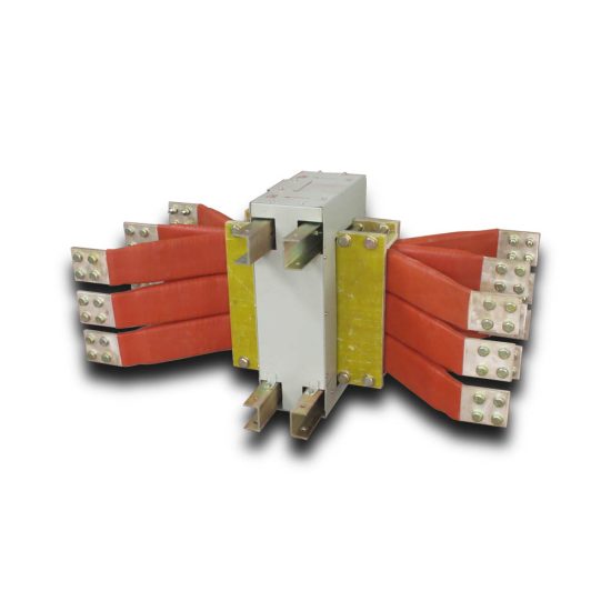
The LJM-1 is a medium-voltage cast-resin current transformer (CT) engineered for precision current measurement and protective relaying in 11kV (IEC) / 10kV (domestic) electrical distribution systems. Designed in strict accordance with IEC 61869-2 and GB/T 20840.2, this device leverages vacuum pressure impregnation (VPI) epoxy resin technology to deliver superior dielectric strength, environmental resilience, and long-term operational stability. Unlike traditional oil-immersed CTs, the LJM-1 eliminates fire hazards, reduces maintenance overhead, and offers compact mechanical dimensions suitable for both indoor switchgear and outdoor pole-mounted installations.
Operating Principle of Cast-Resin Insulation
Cast-resin insulation in the LJM-1 utilizes a cycloaliphatic epoxy resin system cured under vacuum and pressure to fully encapsulate the magnetic core and secondary windings. This process eliminates voids and moisture ingress pathways, achieving a partial discharge level below 10 pC at 1.2 × Um/√3 (where Um = 12 kV). The resin’s high tracking index (>600 V) ensures surface flashover resistance even in polluted or humid environments. Thermal class F (155°C) insulation allows continuous operation at ambient temperatures up to 40°C with a 10K hotspot margin. The monolithic structure provides mechanical rigidity against short-circuit electromagnetic forces—critical for fault currents exceeding 20 kA.
Advantages Over Oil-Immersed Designs
Compared to oil-filled CTs, the LJM-1’s dry-type construction eliminates risks of oil leakage, flammability, and environmental contamination. Its weight is reduced by approximately 35%, simplifying handling during installation. The absence of an oil expansion tank enables vertical or horizontal mounting without orientation constraints. Furthermore, the epoxy matrix exhibits negligible aging under UV exposure, making it ideal for outdoor applications where oil units require sun shields. Dielectric recovery after transient overvoltages is instantaneous due to the solid dielectric’s non-polar nature—unlike oil, which may retain ionized paths post-fault.
Typical Application Overview
The LJM-1 serves dual roles: revenue-grade metering (accuracy classes 0.2S/0.5S) and protection (classes 5P10/5P20). It is commonly deployed in 11kV ring main units (RMUs), pad-mounted transformers, and utility substations. In industrial settings, it interfaces with digital protective relays (e.g., SEL-751) for motor overload and ground-fault detection. Renewable integration projects—such as solar farms feeding into 10kV grids—use the LJM-1 for SCADA telemetry and anti-islanding protection. Its standardized secondary output (typically 1A or 5A) ensures compatibility with legacy and modern instrumentation.
Technical Specifications
The LJM-1’s performance envelope is defined by rigorous electrical and environmental parameters aligned with international standards. Below is a representative specification table for a common variant:
| Parameter | Value |
|---|---|
| Rated System Voltage (IEC) | 11 kV |
| Maximum System Voltage (Um) | 12 kV |
| Domestic Equivalent Voltage | 10 kV |
| Primary Current Ratings | 50–3150 A (standard steps) |
| Secondary Current | 1 A or 5 A |
| Accuracy Classes | Metering: 0.2S, 0.5S; Protection: 5P10, 5P20 |
| Rated Burden | 2.5–30 VA (depending on class) |
| Short-Time Thermal Current | 20 kA for 1 s (Ith) |
| Dynamic Withstand Current | 50 kA peak (Idyn) |
| Power Frequency Withstand Voltage | 28 kV rms, 1 min |
| Lightning Impulse Withstand | 75 kV peak (1.2/50 μs) |
| Insulation Material | VPI cycloaliphatic epoxy resin |
| Magnetic Core | Grain-oriented electrical steel (GOES), M6 grade |
| Ambient Temperature Range | −25°C to +40°C |
| Altitude Limit | ≤1000 m (derating required above) |
Standard Service Conditions
The LJM-1 is rated for standard service conditions per IEC 61869-2: ambient temperature from −25°C to +40°C, relative humidity up to 95% (non-condensing), and installation altitude not exceeding 1000 meters above sea level. At altitudes between 1000–2000 m, the power frequency withstand voltage must be derated by 1% per 100 m increment. For coastal or industrial atmospheres (pollution degree III per IEC 60815), the creepage distance is designed at ≥20 mm/kV (phase-to-ground), ensuring reliable operation under salt fog or chemical exposure. The transformer is not intended for explosive atmospheres unless housed in certified enclosures.
Core and Winding Design Parameters
The magnetic circuit employs M6-grade grain-oriented electrical steel (GOES) laminations, annealed to minimize hysteresis loss (<0.8 W/kg at 1.5 T, 50 Hz). Core cross-section is optimized to maintain flux density below 1.6 T under rated current, preventing saturation during transient overloads. Secondary windings use Class F enameled copper wire (IEC 60317-0-2), wound with interlayer insulation of Nomex® paper. Terminal blocks comply with IEC 60947-7-1, featuring screw-type connectors rated for 10 A continuous and IP2X finger-safe protection. Polarity is marked per IEC 61869-2: reducing polarity with “P1” facing the source and “S1” as the reference secondary terminal.
Typical Applications
The LJM-1’s versatility stems from its dual-certification (IEC and GB) and robust design, enabling deployment across diverse grid architectures.
Substation Secondary Metering
In 11kV/0.4kV distribution substations, the LJM-1 provides accurate current signals to revenue meters (e.g., Landis+Gyr E470) with 0.2S class accuracy. Its low phase error (<±10 minutes at 100% In) ensures compliance with EN 50470-1 for billing purposes. The CT is typically installed on the primary side of the distribution transformer, feeding data to AMI (Advanced Metering Infrastructure) systems. For three-phase configurations, matched sets (ratio tolerance ±0.1%) are supplied to minimize vector group errors in kWh summation.
Industrial Power Distribution
Within manufacturing plants, the LJM-1 monitors feeders supplying large motors (≥250 kW) or arc furnaces. Protection-class variants (5P20) interface with multifunction relays to detect phase unbalance, thermal overload, and short circuits. The 20 kA/1s thermal rating accommodates prospective fault levels common in industrial networks. Its compact footprint (e.g., 180 mm height for 600/5A model) allows retrofitting into existing switchgear without panel modifications. Epoxy resin’s vibration damping also mitigates microphonic noise in high-machinery environments.
Renewable Energy Integration
Solar photovoltaic (PV) farms connected to 10kV grids utilize the LJM-1 for both performance monitoring and grid-code compliance. During anti-islanding tests, the CT must accurately track rapid current changes (di/dt > 100 A/ms); the GOES core’s low remanence ensures minimal residual flux. In wind turbine step-up transformers, LJM-1 units provide inputs to SCADA for real-time power factor correction. Their immunity to DC offset (from inverter harmonics) is validated per IEC 61869-2 Annex D, with ratio error maintained within ±0.5% under 10% DC component.
Rural and Suburban Distribution Networks
For rural electrification projects, the LJM-1’s outdoor-rated design (UV-stabilized resin, IP54 terminal box) supports pole-top installation on 11kV overhead lines. It feeds data to remote terminal units (RTUs) for load profiling and outage management. In suburban ring-main networks, multiple LJM-1 units enable directional earth-fault detection by comparing zero-sequence currents across feeders. The 5P10 class ensures sufficient accuracy at 10× rated current—critical for detecting high-impedance faults common in unearthed systems.
Compliance with International Standards
The LJM-1 is engineered to satisfy both global and regional regulatory frameworks, ensuring interoperability and safety across markets.
IEC 61869-2 Certification Details
IEC 61869-2 governs instrument transformers for AC systems >1 kV. The LJM-1 meets all mandatory clauses: accuracy verification under sinusoidal conditions (Clause 6.3), temperature rise limits (ΔT ≤ 60 K for windings), and dielectric tests per Table 3. Type tests include partial discharge measurement (<10 pC at 1.2 × Um/√3), short-circuit withstand (250 × In for 1 s), and impulse testing (75 kV BIL). Routine tests—performed on every unit—comprise ratio/polarity check, insulation resistance (>1000 MΩ at 2500 V DC), and power frequency withstand (28 kV, 1 min). Certification is issued by accredited bodies such as TÜV or SGS.
Alignment with GB/T 20840.2
GB/T 20840.2 is China’s national adoption of IEC 61869-2, with minor deviations. Key differences include: (1) lightning impulse level set at 75 kV (same as IEC), but power frequency test voltage specified as 32 kV for 10kV systems (vs. IEC’s 28 kV for 11kV); (2) requirement for additional seismic testing (0.3g horizontal acceleration) in earthquake-prone regions; (3) mandatory marking of “GB” logo alongside IEC. The LJM-1 complies with both by designing to the stricter envelope—e.g., using 32 kV test voltage during production even for export units.
Testing and Certification Workflow
Certification involves three phases: design review (verifying FEM simulations of electric field distribution), type testing (conducted in ISO 17025 labs), and factory audit (ensuring process control per ISO 9001). Critical tests include thermal stability (8-hour run at 1.2 × In), followed by accuracy recheck to confirm no degradation. For protection CTs, knee-point voltage (Vk) is measured per IEC 61869-2 Annex C to validate 5P class—e.g., Vk ≥ 100 V for 600/5A, 5P20 unit. Test reports remain valid for five years unless design changes occur.
On-Site Testing Procedures
Post-installation verification ensures the LJM-1 performs within specifications under actual operating conditions.
Insulation Resistance Test
Using a 2500 V DC megohmmeter, measure resistance between primary conductor and grounded case, and between secondary terminals and case. Acceptance criterion: ≥1000 MΩ at 20°C. Correct for temperature using RT2 = RT1 × 2(T1−T2)/10. Low readings indicate moisture ingress or resin cracking—requiring drying or replacement. Perform before and after dielectric tests to detect insulation damage.
Turns Ratio Test
Apply low-voltage AC (5–10 V) to secondary winding and measure induced primary voltage. Calculate ratio as Vp/Vs; compare to nameplate. Tolerance: ±0.25% for 0.2S class, ±1% for 5P class. Alternatively, use a dedicated CT analyzer (e.g., Omicron CT Analyzer) injecting 1–5 A into primary. Verify all taps if multi-ratio.
Polarity Test
Connect a 1.5 V DC battery between P1 and P2. Momentarily close the circuit while monitoring a center-zero galvanometer across S1–S2. A positive kick confirms reducing polarity (standard per IEC). Incorrect polarity causes relay misoperation—e.g., reverse power flow indication. Repeat three times to eliminate contact bounce artifacts.
Power Frequency Withstand Voltage Test
Apply 28 kV rms (50 Hz) between primary and grounded secondary/case for 1 minute. Use a calibrated HV test set with overcurrent trip (≤100 mA). No flashover or sustained discharge constitutes pass. Reduce voltage gradually post-test to avoid resonant overvoltages. Mandatory after transportation or prolonged storage.
Short-Circuit Test for CT
Inject 100–120% of rated primary current and verify secondary output matches burden curve. For protection CTs, extend to 20× In to confirm linear response up to accuracy limit factor (ALF). Monitor secondary voltage—should not exceed 500 V to prevent insulation stress. Record waveform on oscilloscope to detect core saturation (clipped sine wave).
Preventive Maintenance Guide
Proactive maintenance extends service life and prevents unexpected failures.
Periodic Inspection Protocol
Annual visual inspection includes: checking for surface cracks or tracking marks on resin, verifying terminal tightness (torque: 2.5 N·m for M6 screws), and cleaning dust/salt deposits with isopropyl alcohol. Use UV camera to detect corona discharge in darkness. Measure insulation resistance annually—decline >20% from baseline warrants investigation. In coastal areas, inspect every 6 months for salt accumulation.
Maintenance Intervals and Fault Diagnosis
Every 5 years, perform full electrical tests (ratio, polarity, insulation). Common faults include: (1) open secondary circuit—causes core saturation and overheating; (2) moisture ingress—lowers insulation resistance; (3) loose primary connection—creates hot spots detectable via IR thermography (>10K above ambient). Replace if partial discharge exceeds 20 pC during offline testing. Expected service life is 25–30 years with proper maintenance.
| Interval | Action |
|---|---|
| Annually | Visual inspection, IR scan, insulation resistance |
| Every 5 Years | Full electrical tests, PD measurement |
| After Fault | Ratio/polarity check, dielectric test |
Conclusion
The LJM-1 11kV cast-resin current transformer represents a benchmark in medium-voltage instrumentation, combining IEC 61869-2 and GB/T 20840.2 compliance with field-proven reliability. Its VPI epoxy resin encapsulation delivers exceptional dielectric integrity, eliminating the fire and environmental risks associated with oil-filled alternatives. The use of M6-grade GOES core ensures high accuracy across metering (0.2S) and protection (5P20) applications, even under transient fault conditions. With a thermal endurance rating of 20 kA/1s and dynamic withstand of 50 kA, the LJM-1 meets the demanding short-circuit requirements of modern distribution networks. Designed for both indoor switchgear and outdoor pole-top installations, it operates reliably across −25°C to +40°C ambient ranges and altitudes up to 1000 m. Rigorous type and routine testing—including partial discharge verification below 10 pC and ratio tolerance within ±0.25%—guarantee performance consistency. When maintained per the recommended 5-year cycle, the LJM-1 achieves a service life of 25–30 years, offering utilities and industrial users a cost-effective, low-maintenance solution for critical metering and protection functions. Its standardized interface ensures seamless integration with digital relays, revenue meters, and SCADA systems, supporting grid modernization initiatives worldwide.