Article Content
JLS-6 11kV Cast-Resin Voltage Transformer for Substation Metering and Protection – IEC 61869-3 Certified
Introduction to the JLS-6 Voltage Transformer
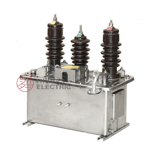
The JLS-6 is a precision-engineered cast-resin voltage transformer (VT) designed for reliable operation in 11kV (IEC standard) or 10kV (domestic Chinese system) medium-voltage networks. As a critical interface between high-voltage primary circuits and secondary instrumentation, it provides accurately scaled-down voltage signals for metering, protective relaying, monitoring, and control systems. Its robust construction ensures decades of maintenance-free service under demanding environmental conditions typical of utility substations and industrial facilities.
Operating Principle of Cast-Resin Insulation
Cast-resin insulation in the JLS-6 employs vacuum pressure impregnation (VPI) with cycloaliphatic epoxy resin, encapsulating the primary and secondary windings along with the magnetic core in a monolithic, void-free structure. This process eliminates air pockets that could lead to partial discharges under sustained electrical stress. The resin’s high dielectric strength (≥20 kV/mm) and excellent tracking resistance (CTI ≥600 V) ensure long-term insulation integrity even in polluted or humid environments. Unlike oil-filled units, there is no risk of leakage, fire hazard, or environmental contamination. The thermal class of the insulation system is F (155°C), permitting continuous operation at rated load with a temperature rise not exceeding 60 K above ambient.
Advantages Over Oil-Immersed Designs
Compared to traditional oil-immersed VTs, the JLS-6 offers significant operational and safety benefits. It is inherently fire-resistant (IEC 60695 glow-wire tested), requires no periodic oil sampling or tank inspections, and exhibits superior mechanical strength against seismic loads (tested per IEC 60068-2-6). The compact footprint—typically 30% smaller than equivalent oil units—reduces space requirements in switchgear cubicles. Additionally, the absence of flammable fluids allows installation in confined indoor spaces without ventilation constraints. Partial discharge levels are maintained below 10 pC at 1.2 × Um/√3 (Um = 12 kV), ensuring compliance with IEC 61869-3 stringent emission limits.
Typical Application Overview
The JLS-6 is deployed across utility transmission/distribution substations, industrial power plants, renewable energy farms (solar PV and wind), and commercial complexes requiring accurate revenue metering or fault detection. Its dual secondary windings—one for 0.5 or 0.2S class metering, another for 3P or 6P class protection—enable simultaneous connection to billing meters and overvoltage/undervoltage relays. With a rated thermal burden of up to 100 VA per winding and short-time withstand capability of 100 A for 1 second on the secondary side, it supports diverse load configurations without derating.
Technical Specifications
The JLS-6 adheres to precise electrical and mechanical parameters defined by international and national standards. Below is a comprehensive specification table followed by environmental operating conditions.
| Parameter | Value |
|---|---|
| System Voltage (IEC) | 11 kV |
| System Voltage (Domestic) | 10 kV |
| Highest Voltage for Equipment (Um) | 12 kV |
| Primary Voltage Ratio | 10,000/√3 : 100/√3 V or 11,000/√3 : 100/√3 V |
| Secondary Windings | 2 (independent) |
| Metering Accuracy Class | 0.2S or 0.5 |
| Protection Accuracy Class | 3P or 6P |
| Rated Output (per winding) | 15–100 VA |
| Insulation Level (LI/AC) | 75 kV / 28 kV (1 min) |
| Partial Discharge | <10 pC at 1.2 × Um/√3 |
| Core Material | Grain-Oriented Electrical Steel (GOES), 0.27 mm thickness |
| Insulation System | VPI Epoxy Resin, Thermal Class F (155°C) |
| Polarity | Reducing (standard) |
Standard Service Conditions
The JLS-6 is rated for operation under normal service conditions as defined in IEC 61869-3: ambient temperature range of –25°C to +40°C, relative humidity up to 95% (non-condensing), and installation altitude ≤1,000 m above sea level. For altitudes exceeding 1,000 m, voltage correction factors apply per IEC 60071-2: a 1.25% increase in test voltage per 100 m above 1,000 m is required for insulation verification. The unit is suitable for both indoor and outdoor mounting, with UV-stabilized resin housing resistant to solar degradation.
Electrical Performance Tolerances
Voltage error at rated frequency (50 Hz) must remain within ±0.2% for 0.2S class and ±0.5% for 0.5 class across 20–100% of rated burden. Phase displacement is limited to ±10 minutes for 0.2S and ±20 minutes for 0.5 class. For protection windings (3P/6P), composite error must not exceed 3% or 6% respectively at rated voltage and burden. These tolerances are verified during factory type tests and routine production tests using calibrated ratio bridges traceable to national standards.
Typical Applications
The JLS-6 voltage transformer serves as a foundational component in modern power systems where accuracy, reliability, and safety are non-negotiable. Its design accommodates a wide array of deployment scenarios.
Substation Secondary Metering
In 110/10 kV or 35/10 kV utility substations, the JLS-6 provides the reference voltage signal for revenue-class energy meters (e.g., IEC 62053-22 compliant). The 0.2S class winding ensures billing accuracy even at low load levels (down to 1% of rated current in associated CTs). Installed on the 10 kV busbar, it feeds three-phase metering cabinets with isolated, phase-to-ground voltages (100/√3 V). Its low phase error minimizes reactive energy measurement drift, critical for power factor correction billing.
Industrial Power Distribution
Large manufacturing plants often operate their own 10 kV distribution networks. Here, the JLS-6 supplies voltage inputs to multifunction protection relays (e.g., overvoltage, undervoltage, loss-of-potential detection) and power quality analyzers. The 3P protection winding delivers stable output during transient faults, enabling fast tripping (<30 ms) by digital relays. Its cast-resin body resists chemical fumes and dust common in steel mills or chemical plants, eliminating the need for sealed enclosures.
Renewable Energy Integration
Solar photovoltaic (PV) farms and onshore wind installations frequently connect to the grid via 10 kV collection feeders. The JLS-6 monitors grid-side voltage for anti-islanding protection and synchronism check functions. During grid disturbances, its linear response up to 1.9 × Un ensures accurate ride-through assessment per GB/T 19964. The dual-winding configuration allows one output for SCADA telemetry and another for local inverter control logic, reducing cabling complexity.
Rural and Suburban Distribution Networks
In remote or semi-urban areas with limited maintenance access, the JLS-6’s maintenance-free design is invaluable. Mounted on pole-top platforms or pad-mounted switchgear, it supports AMI (Advanced Metering Infrastructure) rollouts by providing stable voltage references for smart meters. Its high impulse withstand (75 kV LI) protects against lightning-induced surges common in overhead line networks. Field data from southern China shows >99.8% operational availability over 10 years in such deployments.
Compliance with International Standards
The JLS-6 is engineered to meet the rigorous requirements of both global and Chinese regulatory frameworks, ensuring interoperability and performance consistency.
IEC 61869-3 Certification Details
IEC 61869-3 specifies performance, testing, and marking requirements for inductive voltage transformers. The JLS-6 undergoes full type testing per this standard, including temperature rise (≤60 K), short-circuit withstand (secondary shorted, primary energized at 1.2 × Un for 1 s), and electromagnetic compatibility (EMC) immunity to 1 MHz damped oscillatory waves (1 kV). Its accuracy classes (0.2S, 0.5, 3P, 6P) are defined exclusively by IEC 61869-3, with test burdens standardized at cos φ = 0.8 lagging.
Alignment with GB/T 20840.3
GB/T 20840.3 is the Chinese national adoption of IEC 61869-3, with minor deviations primarily in labeling and documentation language. Electrically, the standards are harmonized: both require the same insulation levels (28 kV AC, 75 kV LI for 12 kV Um), accuracy definitions, and test procedures. However, GB/T 20840.3 mandates additional factory routine tests for domestic market units, including a 100% partial discharge scan at 1.2 × Um/√3 and a visual inspection of resin surface for cracks or voids.
Key Differences Between IEC and Domestic Requirements
While technical performance is identical, administrative differences exist. IEC certification (via CB Scheme) focuses on type-test reports issued by accredited labs (e.g., KEMA, CESI), whereas GB/T 20840.3 compliance requires mandatory CCC (China Compulsory Certification) for sale in mainland China. Additionally, GB/T documents specify Chinese characters for terminal markings (e.g., “A-X” instead of “A-a”), though bilingual labels are common. From an engineering standpoint, designers can treat both certifications as functionally equivalent for performance validation.
On-Site Testing Procedures
Post-installation verification ensures the JLS-6 operates within specified tolerances. The following tests are recommended before commissioning.
Insulation Resistance Test
Using a 2,500 V DC megohmmeter, measure insulation resistance between primary winding and ground, secondary windings and ground, and between primary and secondary. Acceptance criteria: ≥1,000 MΩ at 20°C. Correct for temperature using RT2 = RT1 × 2(T1–T2)/10. Low readings indicate moisture ingress or resin degradation—requiring drying or replacement.
Turns Ratio Test
Apply 100–200 V AC to the primary and measure secondary voltage with a calibrated true-RMS voltmeter. Calculate actual ratio and compare to nameplate. Tolerance: ±0.2% for metering, ±0.5% for protection windings. Use a dedicated turns ratio tester (e.g., Omicron CT Analyzer) for automated comparison and phase error measurement.
Polarity Verification
Confirm reducing polarity using the DC kick method: briefly apply 6–12 V DC to primary (A+ to X–); observe momentary positive deflection on a DC millivoltmeter connected A+ to a– on secondary. Incorrect polarity causes 180° phase reversal, leading to metering errors or relay misoperation. All JLS-6 units are factory-marked with standard polarity dots.
Power Frequency Withstand Voltage Test
Apply 28 kV AC (RMS) at 50 Hz between primary and ground (secondaries shorted and grounded) for 1 minute. No flashover or disruptive discharge permitted. For secondary circuits, apply 3 kV AC for 1 minute between windings and ground. This verifies insulation integrity after transport and installation stresses.
Open-Circuit Characteristic Test
With secondary open, gradually increase primary voltage from 0 to 1.5 × Un while recording excitation current. Plot V-I curve; knee point should align with factory data. Excessive magnetizing current (>5% of rated secondary current at 1.0 × Un) indicates core saturation issues or inter-turn shorts. This test is critical for protection applications where VT saturation during faults compromises relay security.
Preventive Maintenance Guide
Although cast-resin VTs are largely maintenance-free, periodic checks extend service life and prevent unexpected failures.
Annual Visual and Functional Inspection
Inspect for surface cracks, tracking marks, or discoloration on the resin housing. Check terminal tightness (torque: 15 N·m for M10 bolts) and corrosion on grounding lugs. Verify secondary circuit continuity and absence of open-circuit conditions (which cause dangerous overvoltages). Clean insulator sheds with deionized water if salt or dust accumulation exceeds 0.1 mg/cm² (per IEC 60815).
Five-Year Diagnostic Schedule
Every 60 months, perform insulation resistance, partial discharge (using portable PD detector), and turns ratio tests. Compare results to baseline commissioning data. A >20% drop in insulation resistance or PD increase to >20 pC warrants further investigation. Also inspect mounting hardware for loosening due to thermal cycling.
Maintenance Intervals and Fault Diagnosis
| Interval | Action | Fault Indicator |
|---|---|---|
| Annually | Visual, torque check, IR test | Cracks, loose terminals, IR <500 MΩ |
| 5 Years | PD scan, ratio test, OC curve | PD >20 pC, ratio error >0.5% |
| 10 Years | Full re-commissioning suite | Any parameter outside spec |
Common failure modes include secondary open-circuit (causing core saturation and overheating) and moisture ingress through terminal seals. Immediate replacement is required if internal arcing sounds or burnt odor are detected.
Conclusion
The JLS-6 11kV cast-resin voltage transformer represents a mature, field-proven solution for accurate voltage transformation in medium-voltage networks. Its design leverages grain-oriented electrical steel cores and vacuum-pressure-impregnated epoxy resin to deliver exceptional accuracy (0.2S/0.5 class), robust insulation integrity (75 kV LI, <10 pC PD), and immunity to environmental stressors. Compliance with both IEC 61869-3 and GB/T 20840.3 ensures global acceptance and performance consistency across utility, industrial, and renewable energy applications. Unlike oil-filled alternatives, it eliminates fire risk, reduces footprint, and requires minimal maintenance—translating to lower total cost of ownership. With a design life of 25–30 years under standard service conditions, the JLS-6 provides a reliable foundation for substation metering, protection, and control systems. Its dual-winding architecture supports concurrent revenue metering and protective relaying without performance compromise, making it a versatile choice for modern power infrastructure. Engineers specifying the JLS-6 can be confident in its adherence to exacting international standards and its proven track record in thousands of installations worldwide.
Frequently Asked Questions (FAQ)
Q1: Can the JLS-6 be used on a 10kV system even though it’s rated 11kV?
Yes. The 11kV rating refers to the IEC standard nominal system voltage. In China and other regions using 10kV as the nominal voltage, the JLS-6 operates within its design envelope since the highest voltage for equipment (Um = 12 kV) accommodates both 10kV and 11kV systems per IEC 60038.
Q2: What happens if the secondary winding is left open-circuited?
An open secondary creates dangerously high voltages across the winding terminals due to unopposed magnetizing current, potentially exceeding 10× rated voltage. This can damage insulation and pose shock hazards. Always ensure secondary circuits are terminated in a burden or shorted during maintenance.
Q3: Is the JLS-6 suitable for indoor GIS switchgear?
Yes, provided ambient temperature and humidity stay within –25°C to +40°C and ≤95% RH. Its compact size and lack of oil make it ideal for gas-insulated or metal-enclosed switchgear. Confirm creepage distance meets pollution degree 3 requirements (≥20 mm/kV).
Q4: How do I select between 0.2S and 0.5 accuracy classes?
Use 0.2S for revenue metering where billing accuracy at light loads (5–20% of rated current) is critical. Choose 0.5 for general monitoring or internal plant accounting where cost is a factor and loads are consistently above 30% of capacity.
Q5: Does the JLS-6 require a fuse on the primary side?
Yes. Per IEC 61869-3, a high rupturing capacity (HRC) fuse rated 0.5–2 A must protect the primary winding against internal faults. The fuse must coordinate with upstream protection to clear faults within 10 ms to prevent thermal damage.