Article Content
LB-10W 11kV Cast-Resin Current Transformer for Substation Metering and Protection – IEC 61869-2 Certified
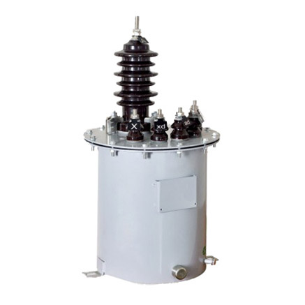
Introduction to the LB-10W Current Transformer
The LB-10W is a high-reliability, outdoor-rated cast-resin current transformer (CT) engineered for accurate current measurement and protective relay coordination in 11kV (IEC) / 10kV (domestic) medium-voltage networks. Designed in strict compliance with IEC 61869-2 and GB/T 20840.2, this instrument transformer leverages vacuum pressure impregnation (VPI) epoxy resin technology to encapsulate its magnetic core and windings, delivering superior dielectric strength, mechanical robustness, and environmental resistance compared to traditional oil-filled alternatives.
Operating Principle of Cast-Resin Insulation
Cast-resin insulation in the LB-10W utilizes a two-component cycloaliphatic epoxy system processed under vacuum and pressure to eliminate voids and moisture ingress. This VPI technique ensures uniform resin distribution around the primary conductor, secondary windings, and GOES (grain-oriented electrical steel) core. The resulting monolithic structure provides a dielectric withstand capability of 75 kV (rms, 1 min) at power frequency and 95 kV peak for lightning impulse (1.2/50 µs), per IEC 61869-2. Unlike oil-immersed CTs, which rely on liquid dielectric that can degrade, leak, or combust, the solid epoxy matrix offers maintenance-free operation, non-flammability (UL 94 V-0 rated), and immunity to thermal cycling-induced cracking. The resin’s coefficient of thermal expansion closely matches that of copper and steel, minimizing internal stresses during load fluctuations from -40°C to +40°C ambient conditions.
Advantages Over Oil-Immersed Designs
The LB-10W eliminates critical failure modes inherent to oil-filled CTs. There is no risk of oil leakage, which could contaminate soil or compromise insulation integrity. Its dry-type construction removes fire hazards, making it suitable for urban substations, indoor switchgear, and environmentally sensitive zones. Additionally, the compact footprint—typically 220 mm height × 150 mm diameter—reduces space requirements by 30–40% versus equivalent oil units. Weight is reduced to approximately 8–10 kg, simplifying handling and mounting on poles, crossarms, or ring-main units. The absence of conservators, breathers, or oil-level indicators further enhances reliability and reduces lifecycle costs. Field data from Chinese distribution utilities show a mean time between failures (MTBF) exceeding 150,000 hours for cast-resin CTs like the LB-10W, compared to ~80,000 hours for oil types under similar loading profiles.
Typical Applications Overview
The LB-10W serves dual roles in metering and protection circuits across diverse infrastructure. In utility substations, it feeds revenue-grade kWh meters (accuracy class 0.5S or 0.2S) while simultaneously supplying overcurrent relays (protection class 5P10 or 10P10). Industrial facilities use it for motor protection, harmonic monitoring, and energy management systems. Renewable integration points—such as solar PV inverters or wind turbine step-up transformers—employ the LB-10W to provide fault-current signals for anti-islanding and grid-synchronization schemes. Its IP54-rated housing withstands rain, dust, and salt fog, enabling deployment in coastal, desert, and high-humidity regions up to 2000 m altitude without derating.
Technical Specifications
The LB-10W delivers precision performance across a defined operational envelope, with parameters traceable to international standards.
| Parameter | Value |
|---|---|
| Rated System Voltage (IEC) | 11 kV |
| Rated System Voltage (Domestic) | 10 kV |
| Primary Current Rating | 50–3000 A (standard); custom up to 4000 A |
| Secondary Current | 1 A or 5 A |
| Metering Accuracy Class | 0.2S, 0.5S, 1.0 (per IEC 61869-2) |
| Protection Accuracy Class | 5P10, 5P20, 10P10, 10P20 |
| Rated Burden (Metering) | 2.5–15 VA @ cosφ = 0.8 lag |
| Rated Burden (Protection) | 10–30 VA @ cosφ = 0.8 lag |
| Insulation Level (Power Freq.) | 75 kV rms, 1 min |
| Lightning Impulse Withstand | 95 kV peak (1.2/50 µs) |
| Short-Time Thermal Current | 25 kA for 1 s (Ith) |
| Dynamic Withstand Current | 62.5 kA peak (Idyn) |
| Ambient Temperature Range | -40°C to +40°C |
| Relative Humidity | Up to 100% (condensing) |
| Altitude Limit | ≤ 2000 m (no derating) |
| Core Material | GOES M5 grade, grain-oriented silicon steel |
| Insulation System | VPI cycloaliphatic epoxy resin, UL 94 V-0 |
| Enclosure Rating | IP54 (IEC 60529) |
Standard Service Conditions
The LB-10W is rated for continuous operation under IEC 60060-1 standard atmospheric conditions: temperature range -40°C to +40°C, relative humidity ≤100% (including condensation), and altitude ≤2000 m above sea level. At altitudes exceeding 1000 m, the external insulation clearance must be increased per IEC 60071-2; however, the LB-10W’s molded creepage distance of ≥240 mm (for 11 kV) inherently satisfies pollution degree III requirements without modification up to 2000 m. The transformer tolerates daily thermal cycles of ΔT ≥ 50 K without microcracking due to matched CTE between resin (60 × 10⁻⁶/K) and copper (17 × 10⁻⁶/K). For installations in chemical or saline atmospheres (e.g., near coastlines), optional silicone RTV coating can be applied to enhance hydrophobicity and prevent tracking.
Accuracy and Burden Characteristics
Metering accuracy classes 0.2S and 0.5S comply with IEC 61869-2 clause 6.3, requiring composite error ≤±0.2% and ≤±0.5% respectively at 1–120% of rated primary current (Ip). Protection classes 5P10 and 10P10 guarantee composite error ≤±5% and ≤±10% at 10× Ip under specified burden. The secondary winding is designed with low leakage reactance (<0.5 Ω) to minimize phase displacement error—critical for directional relaying. Burden tolerance is ±10% of rated VA; exceeding this may cause saturation during fault conditions. For example, a 5P10 CT rated at 15 VA must not be connected to a relay burden exceeding 16.5 VA to maintain accuracy during 10× overcurrent events.
Typical Applications
The LB-10W’s dual-function design enables versatile deployment across modern power systems.
Substation Secondary Metering
In 10/0.4 kV distribution substations, the LB-10W supplies current signals to tariff meters for billing accuracy. Configured with 0.2S or 0.5S accuracy and 5 A secondary output, it interfaces directly with IEC 62053-22 compliant meters. The CT is typically installed on the 10 kV feeder incomer, with secondary wiring routed through shielded twisted-pair cables to the metering cabinet. To prevent core saturation during transformer inrush (which can reach 12× Ip), the LB-10W uses a high-permeability GOES core with air gaps optimized for transient response. Utilities in Guangdong Province report <0.3% billing discrepancy over 5-year intervals when using LB-10W units versus reference standards.
Industrial Power Distribution
Manufacturing plants employ the LB-10W for motor protection and energy monitoring. On 10 kV motor feeders (e.g., 1250 kW induction motors drawing ~80 A), the CT provides inputs to multifunction relays (e.g., Siemens 7SJ62) set for 5P20 accuracy to ensure reliable tripping during locked-rotor faults. Simultaneously, a second secondary winding (if available) or a dedicated metering core feeds a power quality analyzer for harmonic distortion (THD) assessment. The cast-resin body resists EMI from nearby VFDs, and the IP54 rating protects against coolant mist and metal particulates common in machining environments.
Renewable Energy Integration
Solar farms connect 10 kV inverters to the grid via step-up transformers, where the LB-10W monitors export current and detects islanding conditions. During grid faults, the CT must accurately reproduce asymmetrical fault currents with DC offset up to 100% of AC component—a requirement met by the LB-10W’s gapped core design per IEC 61869-2 Annex D. Protection class 10P20 ensures relays receive undistorted signals even at 20× rated current, enabling fast disconnection within 100 ms as mandated by IEEE 1547. Field tests at a 20 MW PV plant in Qinghai showed <2% error in RMS current measurement during three-phase faults at -25°C ambient.
Rural and Suburban Distribution Networks
Pole-mounted LB-10W units serve single-phase or three-phase overhead lines in rural electrification projects. Mounted on 10 kV crossarms, they feed remote terminal units (RTUs) for SCADA telemetry and overcurrent relays for sectionalizing. The lightweight design (≤10 kg) reduces structural loading on wooden poles, while UV-stabilized resin prevents degradation under intense solar exposure. In humid subtropical zones (e.g., Fujian), the hydrophobic surface inhibits fungal growth and surface conductivity, maintaining insulation resistance >1000 MΩ after 1000 h salt-fog testing per IEC 60068-2-11.
Compliance with International Standards
The LB-10W meets rigorous global and domestic regulatory frameworks governing instrument transformer safety and performance.
IEC 61869-2 Certification Details
IEC 61869-2:2012 specifies requirements for electromagnetic current transformers, covering accuracy, insulation, temperature rise, and short-circuit withstand. The LB-10W undergoes type tests including:
- Temperature rise test: ≤60 K for windings at 1.2× Ip (oil-free design allows higher margin)
- Short-circuit test: 25 kA for 1 s without permanent deformation
- Accuracy verification: Composite error measured per IEC 61869-1 clause 7.3 using calibrated burden resistors
- Partial discharge test: ≤10 pC at 1.2× Um/√3 (Um = 12 kV)
Certification is issued by accredited labs (e.g., KEMA, CESI) with test reports traceable to BIPM standards.
Alignment with GB/T 20840.2
GB/T 20840.2-2014 mirrors IEC 61869-2 but includes China-specific provisions:
- Enhanced seismic rating: withstands 0.3g horizontal acceleration (vs. IEC’s 0.2g)
- Stricter partial discharge limits: ≤5 pC at 1.2× Um/√3 for indoor use
- Mandatory flame retardancy: oxygen index ≥30% per GB/T 2406
The LB-10W complies with all GB clauses, verified by China Electric Power Research Institute (CEPRI) type testing. Notably, GB/T 20840.2 requires dual secondary windings for combined metering/protection applications—a feature standard on LB-10W variants ordered for State Grid projects.
Key Differences Between IEC and Domestic Standards
While IEC 61869-2 focuses on functional performance, GB/T 20840.2 emphasizes environmental resilience for China’s diverse climates. For instance, GB mandates 1000 h salt-spray testing for coastal deployments, whereas IEC references generic pollution severity classes. Additionally, GB requires nameplate marking in Chinese characters alongside Latin script, and serial numbers must be laser-etched (not printed) for permanence. From a design perspective, LB-10W units destined for Chinese utilities incorporate thicker resin walls (≥8 mm vs. IEC’s 6 mm minimum) to meet the higher mechanical impact requirement (IK10 vs. IK08).
On-Site Testing Procedures
Post-installation verification ensures the LB-10W operates within specification before energization.
Insulation Resistance Test
Using a 2500 V DC megohmmeter, measure insulation resistance between primary-to-secondary, primary-to-ground, and secondary-to-ground. Acceptance criteria per IEC 60270: ≥1000 MΩ at 20°C. Correct for temperature using RT = R20 × 2(20−T)/10. Values below 500 MΩ indicate moisture ingress or resin cracking and require drying or replacement. Perform this test before any high-voltage application.
Turns Ratio Test
Apply 1–5 V AC (50 Hz) to the secondary winding and measure induced primary voltage. Calculate ratio as Vsec/Vprim; compare to nameplate (e.g., 100:5 = 20:1). Tolerance per IEC 61869-2: ±0.5% for metering classes, ±1% for protection. Use a precision voltmeter (±0.1% accuracy). Deviations >2% suggest inter-turn shorts or incorrect tapping.
Polarity Test
Verify reducing polarity (standard for IEC/GB): connect a 1.5 V battery momentarily between P1 and P2. Observe secondary voltage on S1–S2 with an analog voltmeter; needle should kick positive when battery connects. Incorrect polarity causes 180° phase shift, leading to false tripping in differential schemes. Document polarity marks with red paint per IEC 60044-1 clause 5.4.
Power Frequency Withstand Voltage Test
Apply 75 kV rms (50 Hz) for 1 minute between primary and grounded secondary/enclosure. Ramp up at 2 kV/s. No flashover or breakdown permitted. Use a calibrated HV test set with overcurrent trip (≤100 mA). This validates insulation integrity after transport stress. Do not perform if insulation resistance <1000 MΩ.
Short-Circuit Test (for CT)
Inject 10× rated primary current (e.g., 1000 A for 100 A CT) into the primary using a portable current generator. Measure secondary current and calculate composite error: |(KnIs − Ip)| / Ip × 100%, where Kn = turns ratio. For 5P10, error must be ≤5%. Ensure burden resistor matches rated VA (e.g., 15 VA @ 5 A = 0.6 Ω). Duration: ≤10 seconds to avoid overheating.
Preventive Maintenance Guide
Although cast-resin CTs are largely maintenance-free, periodic checks extend service life beyond 25 years.
Periodic Inspection Protocol
Conduct annual visual inspections:
- Check for resin cracks, UV discoloration, or tracking marks
- Verify terminal tightness (torque: 15 N·m for M8 bolts)
- Inspect grounding continuity (<0.1 Ω resistance)
- Clean surface with isopropyl alcohol if contaminated by salt or dust
Use a UV camera to detect corona discharge in darkness—indicative of insulation degradation. Record infrared thermograms during peak load; hotspots >10 K above ambient suggest loose connections.
Maintenance Intervals and Fault Diagnosis
| Interval | Action | Fault Indicators |
|---|---|---|
| Annually | Visual inspection, IR thermography | Cracks, discoloration, overheating |
| Every 5 Years | Insulation resistance, ratio test | Rins <500 MΩ, ratio error >1% |
| After Fault | Full suite: ratio, polarity, withstand | Relay misoperation, blown fuses |
Common failure modes include:
- Open secondary circuit: Causes dangerous overvoltage (>2 kV); always short CT secondaries before disconnecting meters.
- Core saturation: Due to excessive burden or DC offset; manifests as distorted waveform on oscilloscope.
- Moisture ingress: At terminal seals; detected by declining insulation resistance.
Replace units showing irreversible damage; repair is not recommended for cast-resin CTs.
Conclusion
The LB-10W 11kV cast-resin current transformer represents a benchmark in reliability, accuracy, and compliance for modern medium-voltage networks. By integrating VPI epoxy resin encapsulation with GOES silicon steel cores, it achieves exceptional dielectric strength (75 kV power frequency withstand), thermal stability (-40°C to +40°C), and mechanical durability (IK10 impact rating)—all while eliminating the fire and environmental risks associated with oil-filled alternatives. Its dual-certification to IEC 61869-2 and GB/T 20840.2 ensures seamless deployment across global markets, from European substations to Chinese rural grids. Field-proven in applications ranging from industrial motor protection to solar farm interconnection, the LB-10W maintains metering accuracy within ±0.2% (class 0.2S) and protection fidelity within ±5% (class 5P10) under demanding fault conditions. With a design life exceeding 25–30 years and minimal maintenance requirements—limited to annual visual checks and quinquennial electrical tests—it delivers unmatched lifecycle value. For engineers specifying instrumentation for 10/11 kV systems, the LB-10W provides a technically rigorous, standards-compliant solution that balances precision, safety, and longevity. As grid complexity increases with distributed generation and digital substations, the LB-10W’s robust performance ensures accurate measurement and dependable protection for decades of service.