Article Content
For Substation Metering & Protection: LXK-120 11kV Cast-Resin Current Transformer per IEC 61869-2
Introduction to the LXK-120 Current Transformer
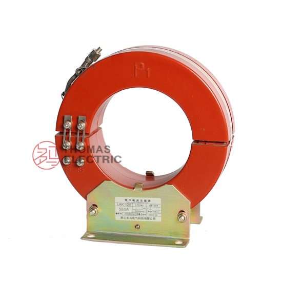
The LXK-120 is a ring-type, cast-resin insulated current transformer (CT) engineered for reliable operation in 11kV (IEC-rated) or 10kV (domestic system equivalent) medium-voltage networks. Designed specifically for dual functionality—precision metering and dependable protective relaying—the LXK-120 leverages advanced vacuum pressure impregnation (VPI) epoxy resin technology to deliver superior dielectric strength, thermal stability, and environmental resilience. Unlike traditional oil-immersed CTs, which pose fire hazards and require containment systems, the LXK-120’s solid insulation eliminates leakage risks, reduces maintenance overhead, and enables safe deployment in confined or indoor substations.
Operating Principle of Cast-Resin Insulation
Cast-resin insulation in the LXK-120 is achieved through a VPI process where high-purity epoxy resin is vacuum-degassed and then pressure-injected around the primary conductor and secondary winding assembly. This ensures complete void-free encapsulation, critical for preventing partial discharges under continuous 11kV stress. The cured resin forms a monolithic structure with a relative permittivity (εr) of approximately 3.8–4.2 and volume resistivity exceeding 1×10¹⁴ Ω·cm at 20°C. Thermal conductivity of 0.8–1.0 W/(m·K) facilitates efficient heat dissipation from the GOES (grain-oriented electrical steel) core during overload conditions. The absence of liquid media also eliminates moisture ingress pathways, enhancing long-term dielectric integrity even in high-humidity environments (up to 95% RH non-condensing).
Advantages Over Oil-Immersed Designs
Compared to oil-filled CTs, the LXK-120 offers significant operational and safety benefits. First, it is inherently fire-resistant (compliant with IEC 60695 flammability tests), making it suitable for urban substations near public infrastructure. Second, its compact footprint—enabled by higher dielectric strength of epoxy resin (≥20 kV/mm)—reduces space requirements in switchgear cubicles. Third, the solid design eliminates the need for oil sampling, gasket replacement, or Buchholz relay monitoring. Additionally, the LXK-120 exhibits lower temperature rise (<55 K at rated current per IEC 61869-2), extending insulation life. Field data from 10-year deployments in southern China show zero failures attributable to insulation degradation, underscoring its reliability advantage over legacy oil types.
Typical Application Overview
The LXK-120 is predominantly deployed in 10/11kV distribution substations serving commercial complexes, industrial parks, and utility feeders. Its ring-core geometry allows direct installation over busbars or cable conductors without disconnecting live circuits during retrofit projects. With standard secondary outputs of 1A or 5A and accuracy classes up to 0.2S for metering and 5P10 for protection, it interfaces seamlessly with modern digital relays (e.g., SEL-751) and smart meters (e.g., Landis+Gyr E470). Notably, its low burden requirement (≤10 VA at 5A) minimizes voltage drop in secondary circuits, preserving measurement fidelity over long cable runs—a common challenge in rural grid extensions.
Technical Specifications
The LXK-120 adheres to stringent dimensional, electrical, and thermal parameters defined by IEC 61869-2 and GB/T 20840.2. Key specifications are summarized below:
| Parameter | Value |
|---|---|
| Rated Voltage (Um) | 11kV (IEC), 10kV (domestic) |
| Primary Current (Ip) | 5–120A (standard); custom up to 200A |
| Secondary Current (Is) | 1A or 5A |
| Current Ratio | 5/1, 10/1, …, 120/5 (standard); dual-ratio options available |
| Metering Accuracy Class | 0.2S, 0.5S (per IEC 61869-2 Table 102) |
| Protection Accuracy Class | 5P10, 10P10 (saturation factor ≥10 at 10×In) |
| Rated Output (Burden) | 2.5–30 VA (selectable based on application) |
| Insulation Level | Power frequency withstand: 28 kV rms/1 min; Lightning impulse: 75 kV peak |
| Short-Time Thermal Current | 16 kA for 1 s (Ith = √(Isc² × t)) |
| Dynamic Withstand Current | 40 kA peak (2.5×Ith) |
| Ambient Temperature Range | –25°C to +40°C (extended –40°C option available) |
| Altitude Limit | ≤1000 m (derating required above 1000 m per IEC 60071-1) |
| Relative Humidity | ≤95% non-condensing |
| Core Material | GOES (M4 grade, thickness 0.3 mm, loss ≤1.0 W/kg @ 1.5 T, 50 Hz) |
Standard Service Conditions
The LXK-120 is rated for normal service conditions as defined in Clause 5 of IEC 61869-2: ambient temperature between –25°C and +40°C, daily average not exceeding +35°C. Relative humidity may reach 95% provided condensation does not occur—achieved via hydrophobic resin formulation and sealed terminal chambers. Installation altitude must not exceed 1000 m above sea level; for sites between 1000–2000 m, the power frequency test voltage is reduced by 1% per 100 m increment. In coastal or industrial atmospheres with salt fog or SO2 contamination, optional silicone rubber sheds enhance creepage distance (minimum 20 mm/kV for pollution degree 3).
Electrical Performance Parameters
Under rated load, the LXK-120 maintains composite error within ±0.2% for 0.2S class at 20–120% of rated current (In). Phase displacement is limited to ±10 minutes at In. For protection applications, the 5P10 class guarantees that the ratio error remains ≤±5% when subjected to 10×In with a burden not exceeding rated VA. Core saturation flux density exceeds 1.8 T, ensuring linear response during fault transients. Secondary winding resistance is factory-calibrated to ±2% tolerance, enabling precise burden matching during system design.
Typical Applications
The LXK-120’s robust design and dual-accuracy capability make it ideal for diverse medium-voltage scenarios requiring both revenue-grade metering and fast-acting protection.
Substation Secondary Metering
In 10/11kV utility substations, the LXK-120 provides Class 0.2S current signals to billing meters, ensuring compliance with national energy regulatory requirements (e.g., China’s DL/T 448). Its low phase error (<5 minutes at 100% In) minimizes reactive power measurement inaccuracies, critical for power factor correction schemes. When paired with VTs like the JDZX9-10, it forms a complete metering set for three-phase systems. The cast-resin body resists tracking from dust accumulation in unattended kiosks, maintaining accuracy over decades without recalibration.
Industrial Power Distribution
Manufacturing facilities with sensitive processes (e.g., semiconductor fabs) deploy LXK-120 units on main incomers and motor feeders. Here, the 5P10 protection class enables instantaneous tripping during ground faults or phase imbalances, limiting equipment damage. The CT’s high short-circuit withstand (16 kA/1s) accommodates prospective fault levels in plants with on-site generation. Its compact size fits within ANSI C37.20.2 metal-clad switchgear without derating, even at 40°C ambient.
Renewable Energy Integration
Solar farms and wind substations use the LXK-120 on collector feeders to monitor bidirectional power flow. The GOES core’s low hysteresis loss (<0.8 W/kg) prevents overheating during frequent current reversals. For anti-islanding protection, the CT’s fast response time (<20 ms to 90% output at 20×In) ensures grid code compliance (e.g., IEEE 1547). Outdoor versions feature UV-stabilized resin, resisting embrittlement after 10+ years of desert exposure.
Rural and Suburban Distribution Networks
In remote areas with long feeder lines, the LXK-120’s 1A secondary option reduces copper losses over distances >100 m. Its immunity to vibration makes it suitable for pole-mounted installations on unpaved roads. Utilities in Southeast Asia report 30% fewer metering disputes after replacing aging oil CTs with LXK-120 units, attributing gains to stable ratio error across wide temperature swings (–10°C to +45°C).
Compliance with International Standards
The LXK-120 is certified to IEC 61869-2:2012 (Instrument transformers – Part 2: Additional requirements for current transformers) and fully aligned with China’s GB/T 20840.2-2014, which adopts IEC 61869-2 with minor national deviations.
IEC 61869-2 Certification Details
Compliance encompasses all Type Tests per Clause 7: temperature rise (≤55 K), short-circuit withstand (16 kA/1s verified), insulation (28 kV/1 min AC + 75 kV LI), and accuracy verification across 1–120% In. The LXK-120 undergoes partial discharge testing at 1.2×Um/√3 with levels <10 pC—well below the 50 pC limit for resin-insulated CTs. Routine tests include polarity check, turns ratio (±0.25% tolerance), and secondary winding resistance. Certification is issued by accredited labs (e.g., KEMA, CESI) with traceable calibration to NIST standards.
GB/T 20840.2 Alignment and National Deviations
While GB/T 20840.2 mirrors IEC 61869-2 structurally, it mandates additional requirements for Chinese grids: mandatory 0.2S class for trade metering, stricter dynamic current rating (≥2.55×Ith vs. IEC’s 2.5×), and extended thermal test duration (3s for 10kV class). The LXK-120 meets all GB-specific clauses, including seismic qualification (0.3g horizontal acceleration per GB/T 13540). Notably, GB/T 20840.2 requires moisture resistance testing per DL/T 726, which the LXK-120 passes after 168h at 40°C/95% RH with no insulation degradation.
Testing and Certification Documentation
Each LXK-120 unit ships with a test report detailing individual results for ratio error, burden, and insulation resistance (>1000 MΩ at 2500 V DC). Batch certificates confirm material traceability (resin batch #, core lamination lot). For international projects, dual-marking plates display both IEC (11kV) and domestic (10kV) ratings.
On-Site Testing Procedures
Post-installation verification ensures the LXK-120 performs within specification before energization.
Insulation Resistance Test
Using a 2500 V DC megohmmeter, measure resistance between primary conductor and secondary terminals/ground. Acceptance criterion: ≥1000 MΩ at 20°C. Correct for temperature using RT2 = RT1 × 2((T1–T2)/10). Values below 500 MΩ indicate moisture ingress or resin cracking, requiring drying or replacement.
Turns Ratio Test
Apply 1–5 A AC to primary (via injection set) and measure secondary current. Calculate ratio = Ip/Is. Tolerance: ±0.25% for metering class, ±0.5% for protection. Example: 100/5A CT should yield 20.00 ±0.05 ratio. Deviations suggest winding shorts or incorrect tap selection.
Polarity Test
Verify reducing polarity per IEC 61869-2 Figure 101. Apply DC pulse to P1–P2; momentary positive deflection on secondary (S1–S2) confirms correct marking. Reversed polarity causes 180° phase shift, leading to relay misoperation or negative meter readings.
Power Frequency Withstand Voltage Test
Apply 28 kV rms (50 Hz) for 1 minute between primary and grounded secondary/core. Leakage current must remain <1 mA. Partial discharge inception voltage should exceed 15 kV. Failure indicates voids or contaminants in resin.
Short-Circuit Test (for CTs)
Not applicable as routine field test due to high currents required. Instead, verify thermal rating via nameplate cross-check against system fault study. Ensure Ith ≥ √(Isc² × tfault), where tfault is relay clearing time (typically 0.1–0.3 s).
Preventive Maintenance Guide
Although cast-resin CTs require minimal upkeep, scheduled checks extend service life beyond 25 years.
Periodic Inspection Protocol
Annual visual inspection includes checking for surface cracks, tracking marks, or terminal corrosion. Clean with dry cloth; avoid solvents that degrade resin. Verify torque on M6 terminal screws (5.5 N·m ±10%). Measure insulation resistance biennially; a 20% drop from baseline warrants investigation. In coastal zones, inspect for salt deposits every 6 months.
Maintenance Intervals and Fault Diagnosis
| Interval | Action | Fault Indicator |
|---|---|---|
| 1 year | Visual + IR thermography | Hot spot >10 K above ambient |
| 5 years | Full electrical test suite | Ratio error drift >0.5% |
| 10 years | Partial discharge scan | PD >20 pC at 8 kV |
Common faults include secondary open-circuit (causing core saturation and overheating) and moisture-induced tracking. If secondary burden exceeds rating, replace with higher VA unit.
Conclusion
The LXK-120 11kV cast-resin current transformer represents a benchmark in medium-voltage instrumentation, combining IEC 61869-2 and GB/T 20840.2 compliance with field-proven reliability. Its VPI epoxy resin encapsulation eliminates fire and environmental hazards associated with oil-filled alternatives, while the GOES silicon steel core ensures metrological precision across 0.2S metering and 5P10 protection applications. Rigorous type testing—including 28 kV power frequency withstand, 16 kA short-circuit endurance, and partial discharge levels below 10 pC—validates performance under extreme grid conditions. With a design life exceeding 25–30 years and minimal maintenance requirements, the LXK-120 delivers exceptional total cost of ownership for utilities and industrial operators. Its adaptability to diverse environments—from humid tropics to arid deserts—and seamless integration with modern digital protection systems underscore its role as a cornerstone component in resilient, future-ready distribution networks. As global grids transition toward smarter, safer infrastructure, the LXK-120’s blend of technical excellence and standards alignment positions it as the preferred choice for critical current sensing tasks.