Article Content
33kV Cast-Resin Voltage Transformer SZW-35 for Metering and Protection – IEC 61869-3 Standard
Introduction to the SZW-35 Voltage Transformer
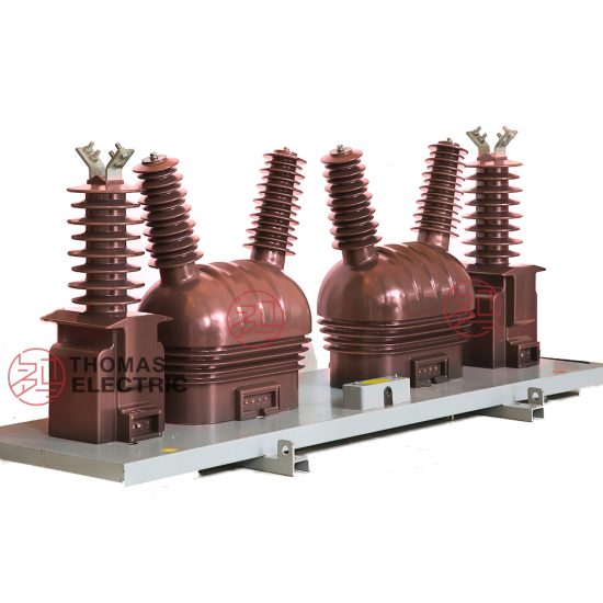
The SZW-35 is a precision-engineered, cast-resin insulated voltage transformer (VT) rated for 33kV primary system voltage (corresponding to 35kV nominal domestic systems). Designed in strict accordance with IEC 61869-3 and GB/T 20840.3, this instrument transformer delivers high accuracy for both metering and protective relaying functions in medium-voltage substations and industrial power networks. Its solid dielectric construction eliminates fire hazards and environmental risks associated with oil-filled units, making it ideal for indoor switchgear, urban substations, and environmentally sensitive installations.
Operating Principle of Cast-Resin Insulation
Cast-resin insulation in the SZW-35 employs vacuum pressure impregnation (VPI) of cycloaliphatic epoxy resin around the primary and secondary windings wound on grain-oriented electrical steel (GOES) cores. This process ensures complete void-free encapsulation, providing superior dielectric strength and resistance to partial discharge (PD) under continuous operating voltage. The resin matrix bonds molecularly with conductor surfaces, preventing moisture ingress and tracking even under polluted or humid conditions. Unlike oil-paper systems, cast-resin insulation exhibits negligible aging under thermal cycling between -40°C and +40°C ambient temperatures, maintaining consistent dielectric performance over decades of service. The absence of liquid insulation also eliminates maintenance requirements related to oil sampling, degassing, or leakage monitoring.
Advantages Over Oil-Immersed Designs
Compared to traditional oil-immersed VTs, the SZW-35 offers significant operational and safety benefits. Its dry-type construction removes explosion and fire risks, satisfying stringent safety codes for indoor installations per IEC 61869-3 Annex D. The compact footprint—typically 30% smaller than equivalent oil-filled units—reduces space requirements in GIS or RMU enclosures. Additionally, cast-resin VTs exhibit lower no-load losses due to optimized GOES core lamination (0.23 mm thickness, 1.7 W/kg at 1.7 T, 50 Hz), contributing to energy efficiency over the transformer’s 25–30 year design life. Environmental compliance is enhanced as the unit contains no PCBs or hydrocarbons, simplifying end-of-life disposal under RoHS and WEEE directives.
Typical Application Overview
The SZW-35 is deployed across utility transmission networks, industrial plants, renewable energy interconnection points, and commercial complexes requiring accurate voltage transformation from 33kV (or 35kV) to standardized secondary levels (e.g., 100/√3 V or 110/√3 V). It supports revenue metering (accuracy class 0.2 or 0.5), protective relaying (3P or 6P classes), and synchro-check functions. Common configurations include single-pole units for phase-to-ground measurement in unearthed or resonant-earthed systems, and three-phase banks for delta or wye-connected secondary circuits. Its robust mechanical design withstands seismic loads up to 0.5g (per IEC 60068-2-57), making it suitable for earthquake-prone regions.
Technical Specifications
The SZW-35 voltage transformer is engineered to deliver precise performance under defined electrical and environmental parameters. All specifications comply with IEC 61869-3:2011 and GB/T 20840.3-2013, ensuring interoperability with global protection and metering systems.
Rated Electrical Parameters
Primary rated voltage: 33 kV (IEC standard) / 35 kV (Chinese domestic system). Secondary rated voltages: 100/√3 V, 110/√3 V, or 100 V (phase-to-phase). Rated voltage factor: 1.2 continuous, 1.5 for 30 seconds (for earth-fault conditions in non-effectively earthed systems). Accuracy classes: 0.2, 0.5 for metering; 3P, 6P for protection. Rated outputs: 10–100 VA per secondary winding (dual or triple secondary options available). Burden compatibility: Power factor 0.8 lagging (metering), 1.0 (protection). Insulation level: LI 170 kV / AC 70 kV (BIL/BSP), per IEC 60071-1. Partial discharge: ≤10 pC at 1.2 × Ur/√3, measured per IEC 60270.
Environmental and Mechanical Ratings
Ambient temperature range: -40°C to +40°C (with derating above +40°C per IEC 61869-1). Relative humidity: Up to 100% (condensation permitted). Altitude: Up to 1000 m above sea level (standard); derating required above 1000 m (e.g., 1% reduction in dielectric strength per 100 m above 1000 m). Pollution degree: III (creepage distance ≥25 mm/kV). Seismic withstand: Horizontal acceleration 0.5g, vertical 0.25g. Enclosure: IP00 (for switchgear mounting) or optional IP23 with terminal box. Weight: Approximately 85–110 kg depending on output configuration. Dimensions: Height 850 mm, width 320 mm, depth 280 mm (typical).
Core and Winding Construction
The magnetic core uses high-permeability GOES (M4 grade, 0.23 mm laminations) annealed to minimize hysteresis loss. Primary winding: Enameled copper wire, continuously transposed for low eddy-current loss. Secondary winding: Double-insulated copper conductors with thermal class F (155°C) insulation. Resin system: Cycloaliphatic epoxy with UV stabilizers and silica filler for thermal conductivity (0.8 W/m·K). Thermal design ensures temperature rise ≤60 K above ambient at rated burden, verified by hot-spot thermocouples during type testing. Short-circuit withstand: Withstands 25× rated current for 1 second without damage (for VTs used in fault-current monitoring applications).
Typical Applications
The SZW-35 voltage transformer serves critical roles across diverse power infrastructure sectors, leveraging its high accuracy, reliability, and environmental resilience.
Substation Secondary Metering
In 35kV distribution substations, the SZW-35 provides phase-to-ground voltage signals to revenue-class kWh meters and power quality analyzers. Configured with dual secondaries (e.g., 0.2 class for billing, 3P for protection), it enables simultaneous metering and relay operation without cross-interference. For example, in a typical Chinese urban substation, three SZW-35 units form a wye-connected bank feeding a multifunction meter (e.g., PM8000 series) with 0.2S accuracy, ensuring compliance with DL/T 448-2016 for trade settlement. The low phase error (<±10 arcmin at 0.2 class) minimizes reactive energy measurement uncertainty.
Industrial Power Distribution Systems
Large manufacturing facilities—such as steel mills or chemical plants—use the SZW-35 for motor protection, bus undervoltage tripping, and harmonic monitoring. Installed in metal-enclosed switchgear (e.g., ABB UniGear ZS1), its compact size allows integration into limited bay spaces. In a recent automotive plant in Jiangsu, SZW-35 VTs feed SEL-351S relays for feeder protection, with 6P accuracy ensuring reliable operation during voltage sags down to 50% of nominal. The resin insulation resists chemical vapors and dust, eliminating the need for hermetic sealing required in oil-filled alternatives.
Renewable Energy Integration
Solar PV and wind farms connecting to 35kV grids rely on the SZW-35 for grid-synchronization and anti-islanding detection. At a 50 MW solar farm in Gansu, SZW-35 units provide 100/√3 V signals to SCADA RTUs and synchrocheck relays (e.g., GE L90), with phase displacement error <±5 arcmin critical for zero-phase-sequence blocking. The VT’s high saturation margin (>2.5× Ur) prevents core distortion during transient overvoltages from inverter switching. Outdoor mounting is facilitated by UV-resistant resin housing and stainless-steel hardware.
Rural and Suburban Distribution Networks
In remote areas with limited maintenance access, the SZW-35’s maintenance-free design ensures long-term reliability. Deployed on pole-top platforms or pad-mounted transformers, it supplies voltage data to distribution automation terminals (DTUs) for fault location and voltage regulation. For instance, in Sichuan province’s mountainous terrain, SZW-35 VTs operate continuously at 2500 m altitude with adjusted creepage (31 mm/kV) and derated output (80% of nameplate), validated by field tests per GB/T 11022.
Hybrid AC/DC Microgrids
Emerging microgrid applications use the SZW-35 for DC-link voltage monitoring via rectifier interfaces. In a university campus microgrid in Guangdong, SZW-35 outputs feed isolated DC converters that generate ±10 V signals for battery management systems (BMS). The VT’s low capacitive coupling (<50 pF between windings) minimizes noise injection into sensitive control circuits, a critical advantage over oil-filled units with higher inter-winding capacitance.
Compliance with International Standards
The SZW-35 is certified to both international and Chinese national standards, ensuring global acceptance and regulatory compliance.
IEC 61869-3 Compliance Details
IEC 61869-3:2011 defines performance, safety, and testing requirements for inductive voltage transformers. The SZW-35 meets all mandatory clauses, including: accuracy verification under burdens from 25% to 100% of rated VA; temperature rise limits (≤60 K for resin); short-circuit withstand capability; and dielectric tests (AC 70 kV for 1 min, LI 170 kV impulse). Type tests conducted at accredited labs (e.g., KEMA, CESI) confirm compliance with composite error limits: ≤0.2% for 0.2 class, ≤3% for 3P class. The standard also mandates marking requirements—SZW-35 nameplates include In, Un, accuracy class, and vector group (e.g., Yn/yn).
GB/T 20840.3 Alignment
GB/T 20840.3-2013 is China’s adoption of IEC 61869-3 with minor national deviations. Key alignments include identical accuracy classes, insulation levels (LI 170/AC 70 kV for 35kV systems), and test procedures. However, GB/T specifies additional requirements: mandatory seismic testing per GB/T 13540, extended thermal endurance testing (1000 h at 130°C), and stricter partial discharge limits (≤5 pC at 1.2 × Ur/√3 for indoor units). The SZW-35 undergoes full type testing at China Electric Power Research Institute (CEPRI) to obtain CMA/CNAS certification, required for State Grid procurement.
Differences Between IEC and Domestic Standards
While harmonized, key differences affect design: GB/T mandates higher creepage distances (25 mm/kV vs. IEC’s 20 mm/kV for pollution degree III); requires dual secondary windings for all new installations (per DL/T 726); and enforces stricter short-time thermal current ratings (31.5 kA for 3 s vs. IEC’s 25 kA for 1 s). Additionally, GB/T 20840.3 references GB/T 1208 for burden definitions, which uses slightly different power factor assumptions (0.8 lag for protection vs. IEC’s 1.0). The SZW-35 is engineered to exceed both sets of requirements, ensuring seamless deployment in export and domestic markets.
On-Site Testing Procedures
Post-installation verification ensures the SZW-35 operates within specified tolerances. All tests follow IEC 61869-3 Annex B and DL/T 726-2019 guidelines.
Insulation Resistance Test
Measure insulation resistance between windings and ground using a 2500 V DC megohmmeter. Acceptance criterion: ≥1000 MΩ at 20°C. Correct for temperature using Rt = R20 × 2(20−t)/10. Low readings indicate moisture ingress or resin cracking. For new units, values typically exceed 5000 MΩ. Perform before and after dielectric tests to detect insulation degradation.
Turns Ratio Test
Apply 100–500 V AC to the primary and measure secondary voltage with a calibrated voltmeter (accuracy class 0.1). Calculate ratio error: [(Up/Us) − N] / N × 100%, where N is nominal ratio. Tolerance: ±0.2% for 0.2 class, ±0.5% for 0.5 class, ±3% for 3P. Use bridge methods (e.g., Kelvin-Varley divider) for highest precision. Avoid excitation above 10% of rated voltage to prevent core saturation.
Polarity Test
Verify reducing polarity per IEC 61869-1 Figure 102. Connect a 6–12 V DC source to primary (H1+ to H2−). Momentarily close the circuit while monitoring secondary with a center-zero galvanometer connected X1+ to X2−. A positive kick confirms correct polarity. Incorrect polarity causes 180° phase shift, leading to relay misoperation or meter reversal. Document results with oscillograms if digital relays are involved.
Power Frequency Withstand Voltage Test
Apply 70 kV AC (RMS) at 50 Hz between primary and grounded secondary/core for 1 minute. Use a test transformer with ≤5% waveform distortion. Monitor for flashover, excessive leakage current (>1 mA), or audible discharge. Reduce voltage gradually post-test. This verifies basic insulation level (BIL) integrity after transport stresses. Do not perform if partial discharge exceeds 10 pC during factory tests.
Open-Circuit Characteristic Test
For VTs, measure secondary voltage vs. primary excitation (5–120% of Ur). Plot magnetization curve to detect core defects or shorted turns. Knee point should exceed 1.5 × Ur. At 100% Ur, no-load current should be ≤0.5% of rated primary current. Deviations >10% indicate core lamination damage or winding faults. Compare with factory baseline curves stored in asset management systems.
Preventive Maintenance Guide
Although cast-resin VTs require minimal maintenance, periodic checks ensure longevity and reliability.
Annual Visual and Electrical Inspection
Inspect for surface cracks, tracking marks, or discoloration on resin housing. Clean with dry cloth—never solvents. Check terminal tightness (torque: 15 N·m for M8 bolts). Measure insulation resistance and compare to baseline. Verify secondary circuit continuity and grounding integrity (resistance <0.1 Ω). Record ambient temperature and load profile for trend analysis. Replace if PD exceeds 20 pC during online monitoring.
Five-Year Comprehensive Maintenance
Perform full suite of commissioning tests (ratio, polarity, insulation). Conduct thermal imaging under load to detect hot spots (>10 K above ambient indicates internal fault). Sample secondary burden impedance to ensure within rated VA. Review historical data for accuracy drift—replace if ratio error exceeds 150% of initial value. Update asset records with test certificates per ISO 55000.
Fault Diagnosis and Replacement Criteria
Common failure modes: Resin delamination (from thermal shock), core corrosion (in high-humidity sites), or terminal oxidation. Symptoms include erratic meter readings, relay false trips, or elevated no-load losses. If open-circuit test shows knee point drop >20%, or insulation resistance falls below 100 MΩ, replace immediately. Never attempt field repair—cast-resin units are sealed for life.
Conclusion
The SZW-35 cast-resin voltage transformer represents a benchmark in medium-voltage instrumentation, combining IEC 61869-3 and GB/T 20840.3 compliance with robust engineering for demanding substation environments. Its VPI epoxy resin insulation ensures fire safety, environmental compatibility, and decades-long service life with minimal maintenance. Precision GOES cores and optimized winding design deliver class-leading accuracy for both revenue metering (0.2/0.5) and protection (3P/6P) applications across 33kV (35kV) networks. Field-proven in utilities, industry, and renewables, the SZW-35 withstands harsh conditions—from high-altitude rural grids to chemically aggressive industrial plants—while maintaining dielectric integrity and metrological stability. With a design life of 25–30 years and full alignment with global standards, it offers a future-proof solution for modern power systems prioritizing safety, accuracy, and sustainability.