Article Content
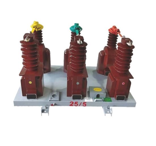
LSZY-35 33kV Cast-Resin Voltage Transformer for Substation Metering and Protection – IEC 61869-3 Certified
Introduction to the LSZY-35 Voltage Transformer
The LSZY-35 is a three-phase, outdoor-rated, cast-resin insulated voltage transformer (VT) engineered for high-accuracy voltage measurement in 33kV (IEC) / 35kV (domestic) power systems. Unlike legacy oil-immersed designs, the LSZY-35 employs vacuum pressure impregnation (VPI) epoxy resin technology to fully encapsulate its primary and secondary windings around a grain-oriented electrical steel (GOES) core. This solid insulation system eliminates fire hazards, prevents oil leakage, and significantly reduces maintenance requirements—making it ideal for urban substations, industrial facilities, and renewable energy interconnection points where safety and reliability are paramount.
Operating Principle of Cast-Resin Insulation
Cast-resin insulation in the LSZY-35 functions by embedding copper windings and the magnetic core within a thermoset epoxy matrix under vacuum and pressure. The VPI process ensures complete void elimination, resulting in uniform dielectric strength and superior partial discharge performance (<5 pC at 1.2 × Um/√3). The resin’s high thermal conductivity (0.8–1.2 W/m·K) enables efficient heat dissipation, while its hydrophobic surface resists moisture ingress even under high humidity (>95% RH). This monolithic structure provides mechanical rigidity against short-circuit electrodynamic forces and seismic loads (up to 0.5g), critical for outdoor installations in seismically active regions. The absence of liquid insulation also eliminates the need for conservators, breathers, or oil sampling—reducing lifecycle costs by up to 40% compared to oil-filled alternatives.
Advantages Over Oil-Immersed Designs
The LSZY-35’s cast-resin construction offers distinct technical advantages over traditional oil-immersed VTs. First, it achieves a higher Basic Insulation Level (BIL) of 170 kV peak for 33kV systems, exceeding the 150 kV BIL typical of oil units. Second, its fire point exceeds 600°C (per IEC 60695-11-10), classifying it as non-flammable—essential for indoor switchgear or densely populated areas. Third, the unit exhibits lower temperature rise (<55 K above ambient at rated load per IEC 61869-3), enhancing long-term insulation life. Additionally, the compact footprint (typically 30% smaller than equivalent oil VTs) simplifies transportation and installation. Environmental compliance is further assured: no PCBs, no oil disposal issues, and full recyclability at end-of-life. These attributes make the LSZY-35 the preferred choice for modern smart substations adhering to IEC 61850 architecture.
Typical Application Overview
The LSZY-35 is deployed across diverse 33/35kV networks requiring precise voltage transformation for metering, protection, and control. Primary applications include utility-owned transmission substations (35/10kV step-down), industrial plant distribution (e.g., steel mills, chemical plants), wind/solar farm collector substations, and rural electrification schemes. Its dual secondary windings—one for 0.2/0.5 class metering and another for 3P/6P class protection—enable simultaneous connection to revenue meters and protective relays without cross-interference. The transformer’s robust design withstands transient overvoltages from switching surges or lightning (tested per IEC 60060-1), ensuring uninterrupted operation during grid disturbances. With an expected service life of 25–30 years under standard conditions, the LSZY-35 delivers exceptional total cost of ownership for critical infrastructure.
Technical Specifications
The LSZY-35 is engineered to meet stringent electrical and environmental performance criteria as defined by IEC 61869-3 and GB/T 20840.3. Below is a comprehensive specification table followed by detailed service condition parameters.
| Parameter | Value |
|---|---|
| Model | LSZY-35 |
| System Voltage (IEC) | 33 kV |
| System Voltage (Domestic) | 35 kV |
| Rated Primary Voltage | 33,000 / √3 V |
| Rated Secondary Voltages | 100 / √3 V (metering), 100 / √3 V (protection) |
| Voltage Ratio | (33,000 / √3) / (100 / √3) = 330:1 |
| Accuracy Class (Metering) | 0.2 (burden ≤ 30 VA), 0.5 (burden ≤ 50 VA) |
| Accuracy Class (Protection) | 3P (burden ≤ 50 VA), 6P (burden ≤ 100 VA) |
| Rated Output (per winding) | 50 VA (metering), 100 VA (protection) |
| Insulation Level (Um) | 36 kV |
| Lightning Impulse Withstand (BIL) | 170 kV peak |
| Power Frequency Withstand (1 min) | 70 kV rms |
| Partial Discharge | <5 pC at 1.2 × Um/√3 |
| Core Material | Grain-Oriented Electrical Steel (GOES), 0.27 mm thickness |
| Insulation System | VPI Epoxy Resin (Class F, 155°C) |
| Phase Configuration | Three-phase, star-connected with neutral |
| Polarity | Reducing polarity (IEC 61869-3 compliant) |
Standard Service Conditions
The LSZY-35 is rated for continuous operation under the following ambient conditions per IEC 60060-1 and GB/T 11022: ambient temperature range of –25°C to +40°C (with 24-hour average not exceeding +35°C); relative humidity up to 95% at +25°C; altitude ≤ 1,000 m above sea level (for altitudes >1,000 m, derating applies per IEC 60071-2: 1% per 100 m above 1,000 m for insulation levels). The unit is designed for outdoor installation with IP23 protection rating at the terminal box, resisting rain ingress at angles up to 60° from vertical. Pollution severity is classified as Medium (creepage distance ≥ 25 mm/kV for 33kV phase-to-ground), suitable for industrial or coastal environments with periodic cleaning recommended in high-salinity zones.
Thermal and Dielectric Performance
Under continuous rated load, the LSZY-35 exhibits a temperature rise of ≤55 K above ambient for windings (measured by resistance method per IEC 60076-2), well below the 100 K limit for Class F insulation. This conservative thermal design extends insulation life by minimizing thermal aging (Arrhenius law). Dielectric integrity is validated through rigorous testing: power frequency withstand at 70 kV rms for 60 seconds with no flashover or disruptive discharge; lightning impulse test at ±170 kV peak (1.2/50 μs wave) with ≤30% residual voltage deviation. The transformer’s capacitance to ground is typically 250–350 pF per phase, enabling accurate modeling in electromagnetic transient programs (EMTP) for resonance studies.
Typical Applications
The LSZY-35 serves as a foundational component in modern medium-voltage infrastructure, providing reliable voltage signals for critical secondary systems. Its dual-winding architecture supports concurrent metering and protection functions without compromise.
Substation Secondary Metering
In 35/10kV utility substations, the LSZY-35 supplies precision voltage inputs to revenue-class kWh meters (accuracy class 0.2S or 0.5S per IEC 62053-22). The metering secondary winding (rated 50 VA at 0.2 class) maintains ratio error within ±0.2% and phase displacement ≤10 minutes under burdens from 2.5 to 100% of rated VA. This accuracy is maintained even during light-load conditions (e.g., nighttime residential demand), ensuring fair billing across dynamic load profiles. The transformer’s low harmonic distortion (<0.5% THD at 100% load) prevents metering errors in networks with nonlinear loads (e.g., variable frequency drives). Installation typically involves mounting on a concrete pad adjacent to 35kV busbars, with shielded twisted-pair cables routed to the metering cabinet to minimize EMI.
Industrial Power Distribution
Heavy industries such as mining, cement production, and petrochemical plants utilize the LSZY-35 for both process monitoring and equipment protection. In a typical 35kV motor control center (MCC), the protection winding (100 VA at 3P class) feeds voltage inputs to distance relays (e.g., IEC 61850-7-4 compliant IEDs) for backup overcurrent and undervoltage tripping. The 3P accuracy class guarantees composite error ≤3% at 5% of rated voltage—critical for detecting incipient faults like single-phase open conductors. The cast-resin housing withstands harsh environments: dust (IP54 with optional gasket), chemical fumes (resin resistant to SO₂ and H₂S per IEC 60068-2-42), and vibration from nearby machinery. Redundant VTs are often installed for N+1 reliability in continuous-process facilities.
Renewable Energy Integration
Wind and solar farms employ the LSZY-35 at the point of interconnection (POI) to provide grid-compliant voltage signals for SCADA and protection systems. For a 50 MW solar plant, multiple LSZY-35 units monitor collector bus voltage (35kV) to enable anti-islanding detection (IEEE 1547) and reactive power control (Q(V) droop). The fast response time (<20 ms to 90% of final value during step changes) ensures timely tripping during grid faults. Crucially, the VT’s low remanence (<5% of saturation flux density) prevents core saturation during DC-offset fault currents—a common issue with conventional VTs that causes relay misoperation. The outdoor design operates reliably in extreme climates, from desert heat (+50°C ambient with solar radiation) to alpine cold (–40°C with ice loading).
Rural and Suburban Distribution Networks
In rural electrification projects, the LSZY-35 enables cost-effective voltage monitoring on lightly loaded 35kV feeders. Its high accuracy at low burdens (e.g., 5 VA for remote RTUs) allows integration with low-power telemetry systems without auxiliary transformers. The unit’s self-extinguishing resin meets fire safety codes for pole-mounted or pad-mounted installations near residential areas. Maintenance-free operation is particularly valuable in remote locations with limited technician access—eliminating oil top-ups or moisture checks required by oil-filled VTs. For suburban ring-main units (RMUs), compact variants of the LSZY-35 fit within SF₆-insulated switchgear bays, providing voltage signals for automated sectionalizing during outages.
Compliance with International Standards
The LSZY-35 is certified to both international (IEC) and Chinese national standards, ensuring global interoperability and regulatory acceptance.
IEC 61869-3 Compliance Details
IEC 61869-3:2011 (“Instrument transformers – Part 3: Additional requirements for inductive voltage transformers”) defines performance, testing, and marking requirements for VTs. The LSZY-35 meets all mandatory clauses: accuracy verification under sinusoidal voltage (Clause 6.3), temperature rise limits (Clause 6.4), short-circuit withstand (Clause 6.6), and insulation coordination (Clause 6.7). Key tests include the voltage factor test (1.5 × rated voltage for 30 s without damage) and the ferroresonance test (stable operation under capacitive loading per Annex C). Markings on the nameplate comply with Clause 8: model, serial number, rated voltages, accuracy classes, and vector group (Ynyn0). Type tests were performed at an ISO/IEC 17025-accredited laboratory, with routine tests conducted on every unit per Clause 9.
GB/T 20840.3 Alignment
GB/T 20840.3-2013 (“Instrument transformers – Part 3: Additional requirements for inductive voltage transformers”) harmonizes with IEC 61869-3 but includes China-specific provisions. The LSZY-35 satisfies GB/T 20840.3’s stricter partial discharge limits (<3 pC at 1.2 × Um/√3 vs. IEC’s <5 pC) and enhanced seismic requirements (horizontal acceleration 0.3g for Zone II per GB 50260). Domestic certification requires type testing by China Electric Power Research Institute (CEPRI), including a 168-hour thermal stability test at 1.1 × rated voltage. The nameplate includes Chinese characters for “电压互感器” and domestic voltage designation (35kV), alongside IEC markings. Notably, GB/T 20840.3 mandates a minimum creepage distance of 25 mm/kV for outdoor pollution degree III—achieved via optimized shed profile on the LSZY-35’s resin housing.
Key Differences Between IEC and Domestic Standards
While IEC 61869-3 focuses on functional performance, GB/T 20840.3 emphasizes environmental resilience for China’s diverse geography. For example, GB/T requires salt fog testing (1,000 hours per GB/T 2423.17) for coastal deployments, whereas IEC references general corrosion standards (IEC 60068-2-52). Accuracy class definitions are identical, but GB/T specifies additional burden combinations for protection windings (e.g., 100 VA at cos φ = 0.8 lagging). Another distinction lies in terminal markings: GB/T uses “a, n” for secondary terminals, while IEC permits “1a, 1n”. The LSZY-35 accommodates both via dual-marked terminals. Certification documentation includes separate test reports for IEC (issued by TÜV) and GB/T (issued by CEPRI), facilitating export and domestic procurement.
On-Site Testing Procedures
Post-installation commissioning of the LSZY-35 requires five critical tests to verify integrity and performance per IEC 60186 and DL/T 726.
Insulation Resistance Test
Using a 2,500 V DC megohmmeter, measure insulation resistance between primary windings and ground, and between primary and secondary windings. Acceptance criterion: ≥10,000 MΩ at 20°C (corrected per IEEE 43 formula if temperature differs). Values below 5,000 MΩ indicate moisture ingress or resin cracking. Perform before and after the power frequency withstand test to detect insulation degradation. Ensure secondary terminals are shorted and grounded during primary-to-ground measurement to avoid false readings from winding capacitance.
Turns Ratio Test
Apply a low-voltage AC source (50–100 V) to the primary and measure secondary voltage with a calibrated voltmeter (accuracy class 0.1). Calculate actual ratio and compare to nameplate (330:1). Tolerance per IEC 61869-3: ±0.2% for 0.2 class windings, ±0.5% for 0.5 class. For protection windings (3P/6P), tolerance is ±1%. Deviations beyond these limits suggest turn-to-turn shorts or incorrect tap connections. Use a dedicated turns ratio tester (e.g., Omicron TTR300) for automated measurement and phase-angle verification.
Polarity Test
Verify reducing polarity using the DC kick method: connect a 6–12 V battery between primary terminals A and N, with a center-zero galvanometer across secondary terminals a and n. Momentary closure of the battery circuit should produce a positive deflection on the galvanometer. Incorrect polarity (additive) will show negative deflection, indicating reversed secondary leads—critical for differential protection schemes. Alternatively, use an AC polarity tester per IEC 60044-2 Annex B, which measures phase shift between primary and secondary voltages (should be 0° ±1°).
Power Frequency Withstand Voltage Test
Apply 70 kV rms (50 Hz) between primary windings shorted together and grounded tank for 60 seconds. Use a calibrated test transformer with overcurrent trip set at 2× expected capacitive current (typically 10–20 mA). Monitor for flashover, excessive leakage current (>50 mA), or audible discharge. If failed, inspect for surface contamination (clean with isopropyl alcohol) or internal defects. This test validates insulation integrity after transportation stresses. Per DL/T 596, repeat annually during preventive maintenance.
Open-Circuit Characteristic Test
With secondary open-circuited, gradually increase primary voltage from 20% to 120% of rated (6.6 kV to 39.6 kV phase-to-ground) while measuring excitation current. Plot volts vs. amps: the knee-point voltage (where slope increases sharply) should exceed 1.9 × rated voltage (62.7 kV) per IEC 61869-3. Below knee-point, excitation current must be ≤0.5% of rated primary current (0.28 A for 33kV/√3 primary). Excessive magnetizing current indicates core lamination damage or shorted turns. This test is essential for ferroresonance risk assessment in isolated-neutral systems.
Preventive Maintenance Guide
Although cast-resin VTs require minimal maintenance, scheduled inspections ensure decades of reliable service.
Periodic Inspection Protocol
Conduct annual visual and electrical checks: inspect resin housing for cracks, UV degradation (chalky surface), or tracking marks; clean sheds with deionized water if pollution layer exceeds 1 mm thickness; verify terminal tightness (torque: 15 N·m for M10 bolts); and perform insulation resistance and ratio tests as described in Section 5. In coastal areas, inspect for salt deposits quarterly. Record all measurements in a maintenance log for trend analysis—sudden drops in insulation resistance may precede failure. Replace silica gel in the terminal box desiccant breather if color changes from blue to pink (indicating >60% moisture saturation).
Maintenance Intervals and Fault Diagnosis
Adhere to the following schedule:
| Interval | Action |
|---|---|
| Annually | Visual inspection, IR test, ratio test, terminal torque check |
| Every 5 Years | Power frequency withstand test, open-circuit characteristic test, partial discharge scan (if available) |
| After Major Fault | Full suite of commissioning tests plus dissolved gas analysis (DGA) of surrounding air for arcing byproducts |
Common faults include: (1) Secondary open-circuit during operation—causes core saturation and overheating; always short secondary before disconnecting loads. (2) Moisture ingress at terminal seals—evidenced by condensation inside the box; reseal with RTV silicone. (3) External flashover—indicated by carbon tracks on resin; clean and apply RTV coating. Never operate with damaged sheds—replace unit immediately.
Conclusion
The LSZY-35 cast-resin voltage transformer represents the convergence of advanced materials science and precision engineering for 33/35kV applications. By leveraging VPI epoxy resin encapsulation and GOES cores, it delivers unmatched safety, accuracy, and longevity compared to oil-immersed predecessors. Its dual secondary windings—rated for 0.2/0.5 metering and 3P/6P protection—support modern substation automation while maintaining strict compliance with IEC 61869-3 and GB/T 20840.3. Rigorous factory and field testing protocols ensure reliability under electrical, thermal, and environmental stressors, with a design life of 25–30 years under standard operating conditions. For utilities and industrial operators seeking a maintenance-free, fire-safe solution for critical voltage measurement, the LSZY-35 provides a technically superior and economically sustainable choice. Its compatibility with digital substations (IEC 61850-9-2 LE) further future-proofs investments in grid modernization. As global standards increasingly favor dry-type instrument transformers, the LSZY-35 stands as a benchmark for performance and compliance in medium-voltage networks worldwide.