Article Content
IEC 61869-2 Certified 11kV Cast-Resin Current Transformer LJK-100240 for Metering & Protection Applications
Introduction to the LJK-100240 Current Transformer
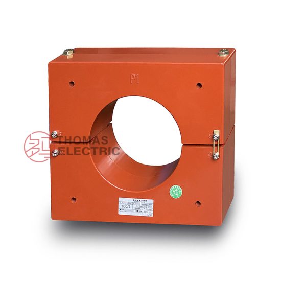
The LJK-100240 is a ring-type, cast-resin insulated current transformer engineered for reliable operation in 11kV (IEC) / 10kV (domestic) medium-voltage (MV) power systems. Designed in strict compliance with IEC 61869-2 and GB/T 20840.2, this device delivers high-accuracy current transformation for both metering and protective relaying functions. Its primary current rating extends up to 240 A, with standardized secondary outputs of 1 A or 5 A, enabling seamless integration into modern substation control and monitoring architectures.
Operating Principle of Cast-Resin Insulation
Cast-resin insulation in the LJK-100240 employs vacuum pressure impregnation (VPI) technology using cycloaliphatic epoxy resin. This process eliminates air voids and moisture ingress pathways by fully encapsulating the GOES (grain-oriented electrical steel) magnetic core and secondary windings under controlled vacuum and pressure conditions. The resulting monolithic structure provides uniform dielectric strength across the entire insulation system. Unlike oil-filled transformers, cast-resin CTs exhibit no risk of leakage, fire hazard, or maintenance-intensive fluid management. The resin’s high tracking resistance (>600 V per IEC 60587) ensures long-term surface insulation integrity even under polluted or humid conditions. Thermal class F (155°C) resin formulation supports continuous operation at ambient temperatures up to 40°C while maintaining mechanical stability over a service life exceeding 25 years.
Advantages Over Oil-Immersed Designs
Compared to traditional oil-immersed current transformers, the LJK-100240 offers significant operational and safety benefits. The absence of flammable insulating oil eliminates fire propagation risks in confined switchgear rooms—a critical consideration for urban substations and industrial facilities. Cast-resin construction provides superior mechanical rigidity, reducing susceptibility to vibration-induced winding displacement during short-circuit events. Additionally, the solid insulation system exhibits negligible aging under partial discharge activity below 10 pC (per IEC 60270), whereas oil-paper systems degrade progressively with repeated discharges. Maintenance requirements are drastically reduced: no oil sampling, gas analysis, or tank sealing inspections are needed. The compact, dry-type design also enables vertical or horizontal mounting without orientation constraints, facilitating flexible switchgear layout optimization.
Typical Application Overview
The LJK-100240 is predominantly deployed in indoor 11kV/10kV switchgear panels serving utility distribution substations, commercial complexes, and heavy industrial plants. Its dual-purpose capability—supporting both Class 0.5S metering accuracy and 5P20 protection accuracy—allows a single unit to feed revenue-grade energy meters and overcurrent relays simultaneously. In renewable energy applications, it monitors grid-tied inverters in solar farms where space constraints favor compact, dry-type transformers. Rural electrification projects benefit from its immunity to temperature cycling and humidity, ensuring stable performance in unattended pole-mounted installations. The transformer’s through-hole diameter accommodates standard busbars up to 60 mm, simplifying retrofit upgrades in legacy infrastructure.
Technical Specifications
The LJK-100240 adheres to stringent dimensional, electrical, and environmental parameters defined by international and domestic standards. All specifications are validated under factory type tests per IEC 61869-2 Clause 7.
| Parameter | Value |
|---|---|
| Model | LJK-100240 |
| System Voltage (IEC) | 11 kV |
| System Voltage (Domestic) | 10 kV |
| Primary Current (Ip) | 5–240 A (adjustable via multi-tap secondary) |
| Secondary Current (Is) | 1 A or 5 A |
| Accuracy Class (Metering) | 0.2S, 0.5S (per IEC 61869-2 Table 101) |
| Accuracy Class (Protection) | 5P10, 5P20 (saturation factor ≥20) |
| Rated Output (Burden) | 2.5–30 VA (at 5 A); 1–15 VA (at 1 A) |
| Insulation Level (LI/AC) | 75 kV / 28 kV (1 min, 50 Hz) |
| Short-Time Thermal Current | 16 kA for 1 s (Ith) |
| Dynamic Withstand Current | 40 kA peak (Idyn) |
| Core Material | GOES M6 grade, 0.3 mm lamination |
| Insulation System | VPI cycloaliphatic epoxy resin, Class F |
| Ambient Temperature Range | −25°C to +40°C |
| Relative Humidity | ≤95% non-condensing |
| Maximum Altitude | 1,000 m above sea level (derating required >1,000 m) |
Standard Service Conditions
The LJK-100240 is rated for continuous operation under IEC 60060-1 standard atmospheric conditions: ambient temperature between −25°C and +40°C, daily average not exceeding +35°C. Relative humidity may reach 95% provided condensation does not occur on the housing surface. Installation altitude must not exceed 1,000 m; beyond this, dielectric strength degrades by approximately 1% per 100 m elevation gain, necessitating derating of the power frequency withstand voltage. In coastal or industrial environments with salt fog or chemical pollutants, the transformer’s hydrophobic resin surface resists electrolytic tracking, but periodic cleaning of terminal surfaces is recommended to maintain creepage distance integrity (minimum 240 mm for 11 kV).
Electrical Performance Parameters
Under rated burden and sinusoidal excitation at 50/60 Hz, the LJK-100240 maintains composite error within ±0.5% for Class 0.5S metering up to 120% of rated primary current. For protection applications, the 5P20 rating guarantees that the ratio error remains ≤±5% at 20× rated primary current with specified burden. The magnetizing impedance at knee-point voltage (typically ≥150 V for 5 A secondary) ensures minimal saturation during fault transients. Secondary winding resistance is precisely controlled to ±2% tolerance to maintain burden compatibility across manufacturing batches. Partial discharge inception voltage exceeds 1.2× Um/√3 (≈7.6 kV) with magnitude <5 pC, well below the 20 pC limit stipulated in IEC 61869-2.
Typical Applications
The versatility of the LJK-100240 enables deployment across diverse MV infrastructure scenarios requiring accurate current sensing and robust fault detection.
Substation Secondary Metering
In 11kV/10kV distribution substations, the LJK-100240 feeds Class 0.5S revenue meters for billing accuracy compliant with EN 50470-1. Its low phase displacement (<10 minutes at 100% Ip) ensures precise power factor measurement critical for reactive energy tariffs. When installed on outgoing feeders, it supports AMI (Advanced Metering Infrastructure) data collection with minimal harmonic distortion impact due to the linear B-H curve of the GOES core up to 1.7 T flux density. Integration with SCADA systems via IEC 61850-9-2 LE sampled values is feasible when paired with compatible merging units.
Industrial Power Distribution
Heavy industries such as steel mills, cement plants, and data centers utilize the LJK-100240 on motor control center (MCC) incomers and large drive circuits. The 5P20 protection class reliably triggers thermal overload relays during locked-rotor conditions without nuisance tripping from inrush currents (typically 6–8× In for 0.2 s). Its high short-time thermal withstand (16 kA/1 s) accommodates prospective fault levels in networks with low source impedance. The cast-resin housing resists EMI from variable-frequency drives, preventing signal corruption in analog 4–20 mA metering loops.
Renewable Energy Integration
Solar photovoltaic (PV) and wind farm collector systems employ the LJK-100240 on 10kV export feeders to monitor real-time generation and detect islanding events. The transformer’s fast response time (<20 ms to 90% of final value) captures transient imbalances during cloud-edge effects or turbine gust responses. Dual secondary windings (e.g., 0.5S/5P20) allow simultaneous connection to revenue meters and anti-islanding relays per IEEE 1547 requirements. Compact dimensions enable installation within pad-mounted transformers where space is constrained.
Rural and Suburban Distribution Networks
In remote or semi-urban areas, the LJK-100240’s maintenance-free operation reduces lifecycle costs for utilities managing extensive feeder networks. Mounted on pole-top reclosers or sectionalizers, it provides fault current data for FLISR (Fault Location, Isolation, and Service Restoration) algorithms. The wide operating temperature range ensures accuracy stability during seasonal extremes—from −25°C winter lows to +40°C summer peaks—without recalibration. Its immunity to moisture ingress prevents insulation degradation in high-humidity climates common in tropical regions.
Compliance with International Standards
The LJK-100240 is engineered to satisfy the rigorous requirements of both global and Chinese regulatory frameworks, ensuring interoperability and safety across markets.
IEC 61869-2 Certification Details
Full compliance with IEC 61869-2:2012 (“Instrument transformers – Part 2: Additional requirements for current transformers”) encompasses type tests for temperature rise, short-circuit withstand, insulation coordination, and accuracy verification. Key certification milestones include: power frequency withstand test at 28 kV RMS for 1 minute with <10 mA leakage current; lightning impulse test (1.2/50 μs) at 75 kV peak with no flashover; and thermal stability test demonstrating ≤55 K temperature rise above ambient at 1.2× Ip. Accuracy validation follows IEC 61869-2 Annex C procedures using calibrated reference standards traceable to national metrology institutes. The 5P20 protection class requires verification of composite error ≤5% at 20× Ip with rated burden connected.
Alignment with GB/T 20840.2
For domestic Chinese deployments, the LJK-100240 meets GB/T 20840.2-2014 (“Instrument transformers – Part 2: Current transformers”), which largely harmonizes with IEC 61869-2 but includes localized requirements. Notably, GB/T mandates a minimum short-time thermal current of 16 kA/1 s for 10 kV class devices—identical to the LJK-100240’s rating—and specifies creepage distance ≥20 mm/kV for pollution degree 3 environments. The standard also requires factory routine tests for every unit, including turns ratio verification (±0.5% tolerance) and insulation resistance (>1,000 MΩ at 2,500 V DC). While IEC permits 1 A or 5 A secondaries, GB/T strongly recommends 5 A for new installations to align with legacy relay compatibility.
Key Differences Between IEC and Domestic Standards
Although IEC 61869-2 and GB/T 20840.2 share core technical principles, subtle divergences exist in test protocols and documentation. IEC emphasizes probabilistic insulation coordination based on statistical overvoltage models, whereas GB/T adopts deterministic worst-case scenarios for lightning impulse testing. Environmental qualification under IEC references IEC 60721-3-3 climate classes, while GB/T cites GB/T 4798.3 with identical temperature/humidity limits but adds sand-dust exposure requirements for northwestern China deployments. Crucially, GB/T 20840.2 mandates Chinese-language nameplates with GB-specific model numbering (e.g., LMK-10 instead of LJK), though the LJK-100240’s physical and electrical characteristics remain unchanged. Certification bodies like CQC (China Quality Certification) require additional EMC testing per GB/T 17626 series not explicitly called out in IEC 61869-2.
On-Site Testing Procedures
Post-installation verification ensures the LJK-100240 performs within specification before energization. All tests follow IEC 60044-1 (now superseded by IEC 61869-2) field testing guidelines.
Insulation Resistance Test
Using a 2,500 V DC megohmmeter, measure insulation resistance between primary conductor (busbar) and secondary terminals/ground. Acceptance criterion: ≥1,000 MΩ at 20°C. Correct for temperature using RT2 = RT1 × 2(T1−T2)/10. Values below 500 MΩ indicate moisture absorption or resin cracking requiring drying or replacement. Perform before and after power frequency withstand tests to detect insulation damage.
Turns Ratio Test
Apply low-voltage AC (5–10 V) to secondary winding and measure induced primary voltage. Calculate actual ratio as Vs/Vp. Compare against nameplate ratio (e.g., 200:5 = 40:1). Tolerance: ±0.5% for metering class, ±1% for protection class. Use a dedicated ratio tester (e.g., Omicron CT Analyzer) for automated comparison. Deviations >1% suggest inter-turn shorts or incorrect tap selection.
Polarity Test
Verify reducing polarity per IEC 61869-2 Figure 102. Connect DC source (+) to P1 and (−) to P2; connect galvanometer between S1 (+) and S2 (−). Momentary switch closure should produce positive deflection. Incorrect polarity causes 180° phase shift, leading to wattmeter reversal or directional relay misoperation. Document results with timestamped oscillograph traces for audit trails.
Power Frequency Withstand Voltage Test
Apply 28 kV RMS (50 Hz) between primary and grounded secondary/housing for 1 minute. Monitor leakage current with shunt resistor; must remain <10 mA. Gradually ramp voltage at 1 kV/s to avoid transient overstress. Failure criteria: flashover, sustained arcing, or current surge >50 mA. Conduct only after insulation resistance confirms dryness.
Short-Circuit Test (for CT)
Inject 100–120% of rated primary current through busbar using portable current source. Measure secondary current with calibrated clamp meter. Verify linearity across 10–120% Ip range. For protection class, additionally inject 20× Ip (e.g., 4,800 A for 240 A CT) at rated burden; confirm secondary output within ±5% error. Record waveform distortion—THD must be <3% at rated current.
Preventive Maintenance Guide
While cast-resin CTs require minimal upkeep, scheduled inspections prevent latent failures in critical infrastructure.
Periodic Inspection Protocol
Annual visual checks include: (1) housing integrity—no cracks, discoloration, or tracking marks; (2) terminal tightness—torque to 12 N·m for M8 studs; (3) cleanliness—remove dust/salt deposits with lint-free cloth and isopropyl alcohol; (4) grounding continuity—resistance <0.1 Ω between housing and earth bar. Infrared thermography during peak load should show ≤5 K differential between phases. Any hotspot >10 K above ambient warrants immediate investigation for loose connections or core saturation.
Maintenance Intervals and Fault Diagnosis
Table: Recommended Maintenance Schedule
| Interval | Task | Acceptance Criteria |
|---|---|---|
| Annually | Visual inspection, IR scan | No physical damage; ΔT ≤5 K |
| Every 5 Years | Insulation resistance, ratio test | R ≥1,000 MΩ; ratio error ≤±0.5% |
| After Fault Event | Full suite: ratio, polarity, insulation | All parameters within initial tolerances |
Common faults include: (1) Open secondary circuit—causes dangerous overvoltage (>2 kV); always short S1-S2 before disconnecting meters. (2) Core saturation—evidenced by distorted secondary waveform during faults; verify burden does not exceed rating. (3) Moisture ingress at terminal seals—indicated by low insulation resistance; replace gasket kit if housing is serviceable.
Conclusion
The LJK-100240 represents a benchmark in 11kV cast-resin current transformer technology, combining IEC 61869-2 and GB/T 20840.2 compliance with field-proven reliability. Its VPI epoxy resin encapsulation eliminates fire hazards and maintenance burdens associated with oil-filled alternatives, while the GOES silicon steel core ensures metrological precision across metering (0.2S/0.5S) and protection (5P10/5P20) functions. Rigorous type testing validates performance under extreme electrical, thermal, and environmental stressors—from 75 kV lightning impulses to 16 kA short-circuit currents. Deployment across utility substations, industrial plants, and renewable energy sites demonstrates adaptability to diverse operational demands. With a design life of 25–30 years under standard service conditions, the LJK-100240 delivers exceptional lifecycle value through zero-fluid maintenance, compact footprint, and immunity to pollution-induced degradation. As global grids evolve toward digitalization and distributed generation, this transformer’s compatibility with modern protection relays and smart metering systems ensures continued relevance in next-generation MV infrastructure.
Q1: Can the LJK-100240 be used outdoors?
No. The LJK-100240 is rated for indoor use only (IP00 enclosure). Outdoor applications require weatherproof housings per IEC 60529, which this model does not provide.
Q2: What is the maximum allowable burden for 5P20 accuracy?
For 5P20 class, the burden must not exceed the rated VA (e.g., 15 VA at 5 A secondary). Exceeding this increases composite error beyond ±5% at 20× Ip.
Q3: Is the secondary winding short-circuited during transport?
Yes. Factory-supplied shorting links must remain installed until connected to burden. Open-circuit operation risks core saturation and insulation damage.
Q4: How does altitude affect performance?
Above 1,000 m, reduce power frequency withstand voltage by 1% per 100 m. At 2,000 m, test voltage becomes 25.2 kV (28 kV × 0.9).
Q5: Can multiple secondaries be ordered?
Yes. Custom configurations with dual secondaries (e.g., 0.5S for metering + 5P20 for protection) are available upon request.