Article Content
CT-10K 11kV Cast-Resin Current Transformer for Substation Metering and Protection – IEC 61869-2 Certified
Introduction to the CT-10K Current Transformer
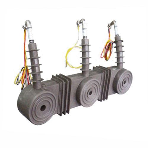
The CT-10K is a medium-voltage, cast-resin insulated current transformer engineered for reliable operation in 11kV (IEC) / 10kV (domestic) power systems. Designed in strict accordance with IEC 61869-2 and GB/T 20840.2, this instrument transformer provides galvanic isolation between high-voltage primary circuits and low-voltage secondary instrumentation, enabling safe and accurate current measurement for metering, protection, and control functions. Its robust construction ensures long-term stability under demanding environmental and electrical conditions typical of utility substations and industrial facilities.
Operating Principle of Cast-Resin Insulation
Cast-resin insulation in the CT-10K employs vacuum pressure impregnation (VPI) of cycloaliphatic epoxy resin around the primary conductor and secondary windings. This process eliminates air voids and moisture ingress pathways, resulting in superior dielectric strength and partial discharge resistance. The resin matrix bonds intimately with the GOES (grain-oriented electrical steel) core laminations and copper windings, creating a monolithic, mechanically rigid structure. Unlike oil-filled alternatives, the solid dielectric system requires no maintenance, poses no fire hazard, and exhibits excellent tracking resistance—even under polluted or humid conditions. The thermal class of the insulation system is rated at 105°C (Class A), supporting continuous operation at ambient temperatures up to 40°C with a 1.2× rated current overload capability for 1 hour without degradation.
Advantages Over Oil-Immersed Designs
Compared to traditional oil-immersed current transformers, the CT-10K offers significant operational and safety benefits. The absence of flammable insulating oil eliminates fire risk, making it suitable for indoor switchgear, urban substations, and confined spaces where fire codes restrict hydrocarbon-based equipment. Its hermetically sealed construction prevents moisture absorption, ensuring stable dielectric properties over decades of service. Additionally, the compact physical footprint—enabled by higher dielectric strength of epoxy resin versus oil-paper systems—reduces space requirements in switchgear panels. Maintenance costs are virtually eliminated, as there are no oil sampling, degassing, or leakage monitoring procedures required. Environmental compliance is also enhanced, as the unit contains no PCBs or other regulated substances.
Typical Applications Overview
The CT-10K is deployed across diverse power infrastructure segments requiring precise current transformation at distribution voltage levels. Primary use cases include revenue metering in utility substations, feeder protection in ring-main units, motor protection in industrial plants, and grid interconnection monitoring for distributed energy resources. Its dual-winding configuration (e.g., 0.5S for metering and 5P20 for protection) allows simultaneous connection to billing-grade meters and overcurrent relays without performance compromise. The transformer’s high accuracy under low-load conditions (down to 1% of rated current) makes it ideal for applications with variable load profiles, such as commercial buildings or solar farms with intermittent generation.
Technical Specifications
The CT-10K is engineered to meet stringent electrical and environmental performance criteria defined by international and domestic standards. Below is a comprehensive specification table followed by detailed subsections addressing key parameters.
| Parameter | Value |
|---|---|
| System Voltage (IEC) | 11 kV |
| System Voltage (Domestic) | 10 kV |
| Rated Primary Current | 50–3000 A (standard steps) |
| Rated Secondary Current | 1 A or 5 A |
| Current Ratio | Customizable (e.g., 600/5, 1200/1) |
| Accuracy Class (Metering) | 0.2S, 0.5S per IEC 61869-2 |
| Accuracy Class (Protection) | 5P10, 5P20 per IEC 61869-2 |
| Rated Output (Burden) | 5–30 VA (metering), 10–50 VA (protection) |
| Short-Time Thermal Current | 20× In for 1 s (e.g., 24 kA for 1200 A CT) |
| Dynamic Withstand Current | 50× In peak (e.g., 60 kA peak for 1200 A CT) |
| Power Frequency Withstand Voltage | 28 kV rms, 1 min (phase-to-earth) |
| Lightning Impulse Withstand Voltage | 75 kV peak (1.2/50 µs) |
| Insulation Material | VPI cycloaliphatic epoxy resin |
| Magnetic Core | GOES silicon steel, grain-oriented |
| Ambient Temperature Range | –25°C to +40°C |
| Altitude Limit | ≤1000 m above sea level (derating above 1000 m) |
| Relative Humidity | ≤95% non-condensing |
Electrical Performance Parameters
The CT-10K’s accuracy classes are validated under IEC 61869-2 test protocols. For metering windings (0.2S/0.5S), composite error must not exceed ±0.2% or ±0.5% at 100% rated current, and remains within ±0.75% even at 1% of rated current—critical for low-load billing accuracy. Protection windings (5P20) guarantee ≤5% composite error at 20× rated current, ensuring reliable relay operation during fault conditions. The rated output (burden) defines the maximum impedance the secondary circuit may present; exceeding this value causes saturation and measurement drift. Standard burdens include 5 VA (for digital meters) and 15–30 VA (for electromechanical relays). The short-time thermal current rating (20×In for 1 s) ensures mechanical integrity during through-faults, while the dynamic withstand (50×In peak) addresses electrodynamic forces from asymmetrical short circuits.
Environmental and Mechanical Ratings
Designed for both indoor and outdoor service, the CT-10K features a UV-stabilized resin housing with creepage distance ≥240 mm for 11kV systems (per IEC 60815 pollution severity Level III). The operating altitude limit is 1000 m; above this, the power frequency withstand voltage must be derated by 1% per 100 m elevation increase. The unit withstands ambient temperatures from –25°C (ensuring resin flexibility during cold starts) to +40°C (with thermal margin for solar loading in outdoor installations). Condensation is prevented via integral moisture barriers in the terminal chamber, and all external hardware uses stainless steel (A2/A4) to resist corrosion. Mounting options include flange-type (for busbar integration) or support brackets for post-type installation.
Typical Applications
The CT-10K serves critical roles across modern power networks where reliability, accuracy, and safety are paramount. Its dual-function design supports concurrent metering and protection needs without cross-interference.
Substation Secondary Metering
In utility-owned 11kV/10kV substations, the CT-10K’s 0.2S or 0.5S metering winding connects directly to revenue-class kWh meters or SCADA RTUs. The high linearity at low currents (1–5% of In) ensures accurate energy accounting during nighttime or weekend low-demand periods. For example, a 1200/5 A, 0.2S CT feeding a Class 0.5S meter achieves overall system accuracy better than ±0.7%, meeting regulatory requirements for billing. The cast-resin body resists tracking from salt fog or industrial pollution near coastal or chemical plant substations, maintaining insulation integrity over decades.
Industrial Power Distribution
Within manufacturing facilities, the CT-10K monitors feeders supplying large motors, transformers, or process lines. Its 5P20 protection winding interfaces with numerical relays (e.g., Siemens 7SJ62) to detect phase faults, ground faults, or overload conditions. The high saturation point (≥20×In) prevents false tripping during motor inrush currents, which can reach 6–8× full-load current for several cycles. In arc furnace or welding plant environments, the robust electromagnetic shielding minimizes interference from harmonic-rich loads, preserving waveform fidelity for protective relaying.
Renewable Energy Integration
Solar photovoltaic (PV) and wind farms utilize the CT-10K at the point of interconnection (POI) to the 11kV grid. Here, it enables both export/import metering (via 0.5S winding) and anti-islanding protection (via 5P10 winding). During cloud transients or wind lulls, the CT maintains accuracy despite rapid current fluctuations, supporting grid code compliance for reactive power control and fault ride-through. The non-flammable design aligns with fire safety mandates for rooftop or ground-mount solar arrays near commercial buildings.
Rural and Suburban Distribution Networks
In pole-mounted or pad-mounted transformers serving residential areas, the CT-10K provides theft detection and load profiling. Utilities install it on outgoing feeders to identify unauthorized tapping or unbalanced loading. The maintenance-free nature reduces truck rolls in remote regions, while the wide temperature tolerance accommodates desert heat or alpine winters. For smart grid deployments, its secondary outputs feed AMI (Advanced Metering Infrastructure) concentrators, enabling real-time load forecasting and outage management.
Compliance with International Standards
The CT-10K is certified to both global and Chinese national standards, ensuring interoperability and regulatory acceptance across markets.
IEC 61869-2 Certification Details
IEC 61869-2 governs the performance, testing, and marking of instrument transformers for frequencies from 15 Hz to 100 Hz. The CT-10K complies with all mandatory clauses, including accuracy verification under sinusoidal steady-state conditions, temperature rise limits (≤60 K for windings), and short-circuit withstand tests. Type tests performed by accredited labs include temperature rise, short-time current, and impulse voltage tests. Routine tests—conducted on every unit—encompass power frequency withstand (28 kV, 1 min), partial discharge (<10 pC at 1.2×Um/√3), and polarity verification. Markings include rated voltage factor (1.2 for 11kV systems), accuracy class, and burden values per IEC 61869-1 general requirements.
Alignment with GB/T 20840.2
GB/T 20840.2 is China’s national adoption of IEC 61869-2, with minor deviations in test voltages and environmental classifications. The CT-10K meets all GB-specific requirements, including a slightly higher power frequency withstand voltage (32 kV for 10kV systems vs. IEC’s 28 kV for 11kV) and mandatory seismic testing for earthquake-prone regions (0.3g horizontal acceleration). Chinese utilities require additional documentation, such as type test reports from CEPRI (China Electric Power Research Institute) and CCC (China Compulsory Certification) markings on the nameplate. The core material must comply with GB/T 2521 for GOES steel, ensuring magnetic losses ≤1.0 W/kg at 1.7 T, 50 Hz.
Key Differences Between IEC and Domestic Standards
While harmonized in principle, practical differences exist. IEC 61869-2 permits 11kV as the standard system voltage, whereas GB/T 20840.2 references 10kV nominal systems—requiring dual labeling on the CT-10K nameplate. Burden notation also varies: IEC uses “VA” (e.g., 15 VA), while older Chinese practices used “Ω” (e.g., 0.6 Ω for 5 A secondary). Modern GB standards now align with IEC on burden expression. Another distinction lies in pollution degree: IEC 60815 defines creepage based on ESDD/NSDD measurements, while GB/T 20840.2 specifies fixed creepage distances (240 mm for 10kV outdoor). The CT-10K exceeds both requirements with a 260 mm creepage path.
On-Site Testing Procedures
Post-installation verification ensures the CT-10K performs within specifications before energization. All tests follow IEC 61869-2 Annex D and IEEE C57.13 guidelines.
Insulation Resistance Test
Using a 2500 V DC megohmmeter, measure insulation resistance between primary-to-secondary, primary-to-ground, and secondary-to-ground. Acceptance criteria: ≥1000 MΩ at 20°C. Correct for temperature using RT = R20 × 2(20–T)/10. Low readings indicate moisture ingress or resin cracking—requiring drying or replacement. Perform before and after high-voltage tests to detect insulation damage.
Turns Ratio Test
Apply a low-voltage AC source (e.g., 10 V) to the primary and measure secondary voltage. Calculate ratio as Vp/Vs; compare to nameplate. Tolerance: ±0.2% for metering class, ±1% for protection class. Use a dedicated ratio tester (e.g., Omicron CT Analyzer) for automated comparison. Deviations beyond tolerance suggest winding shorts or incorrect tap selection.
Polarity Test
Verify reducing polarity per IEC 61869-1: when primary current enters P1, secondary current exits S1. Connect a 1.5 V battery between P1–P2 and a DC milliammeter between S1–S2. A momentary positive deflection confirms correct polarity. Reversed polarity causes 180° phase shift, leading to watt-hour meter reversal or directional relay misoperation.
Power Frequency Withstand Voltage Test
Apply 28 kV rms (for 11kV system) at 50 Hz between primary and grounded secondary/frame for 1 minute. Monitor for flashover, excessive leakage current (>1 mA), or audible discharge. Use a calibrated test transformer with overcurrent trip set at 2× expected capacitive current. This validates dielectric integrity after transportation stresses.
Secondary Winding Resistance and Burden Verification
Measure DC resistance of each secondary winding with a 4-wire micro-ohmmeter. Compare to factory data (±5% tolerance). Then calculate actual burden: Zb = Rwinding + Rlead + Zload. Ensure Zb ≤ rated burden (e.g., 15 VA for 5 A = 0.6 Ω). Excessive burden causes saturation during faults, compromising protection coordination.
Preventive Maintenance Guide
Although cast-resin CTs require minimal maintenance, periodic checks extend service life and prevent unexpected failures.
Annual Visual and Electrical Inspection
Inspect for surface cracks, tracking marks, or discoloration on the resin housing—indicative of partial discharge or UV degradation. Check terminal tightness (torque: 2.5 N·m for M6 screws) and corrosion on grounding connections. Perform insulation resistance and ratio tests annually in critical applications (e.g., hospital backup feeders). Record trends; a 20% drop in insulation resistance warrants further investigation.
Five-Year Comprehensive Maintenance Schedule
Every 60 months, conduct partial discharge measurement (<20 pC at 1.2×Um/√3) using an IEC 60270-compliant detector. Verify thermal imaging under 50% load to detect hot spots (>10 K above ambient suggests internal defects). Clean housing with isopropyl alcohol to remove conductive dust layers that could initiate surface flashover. Update test records in the asset management system for lifecycle analysis.
Fault Diagnosis and Troubleshooting
Common issues include open-circuited secondaries (causing dangerous overvoltages), core saturation (from excessive burden), and moisture-induced tracking. If a connected relay malfunctions, first check secondary continuity and burden. An open CT secondary generates voltages >1000 V—always short-circuit secondaries before disconnecting loads. For accuracy drift, compare ratio test results against baseline; persistent errors indicate core aging or winding damage requiring replacement.
| Maintenance Interval | Activities |
|---|---|
| Initial Commissioning | Full suite of on-site tests (ratio, polarity, insulation, withstand) |
| Annually | Visual inspection, insulation resistance, ratio check |
| Every 5 Years | Partial discharge test, thermal scan, housing cleaning |
| After Major Fault | Repeat short-circuit withstand verification if fault current >15×In |
Conclusion
The CT-10K 11kV cast-resin current transformer represents a benchmark in medium-voltage instrumentation, combining precision engineering with rugged reliability. Its VPI epoxy resin encapsulation and GOES silicon steel core deliver exceptional accuracy—from 1% to 120% of rated current—for both metering (0.2S/0.5S) and protection (5P10/5P20) applications. Full compliance with IEC 61869-2 and GB/T 20840.2 ensures global acceptance, while the maintenance-free design reduces total cost of ownership over a projected service life of 25–30 years. Field-proven in harsh environments—from desert substations to coastal industrial parks—the CT-10K mitigates fire risk, resists pollution, and withstands seismic activity without performance loss. By integrating seamlessly into modern digital substations and renewable energy systems, it supports the transition toward smarter, safer, and more resilient power networks. For engineers specifying instrumentation in 10kV/11kV infrastructure, the CT-10K offers a technically superior, standards-compliant solution that balances performance, safety, and longevity.
Frequently Asked Questions (FAQ)
Q1: Can the CT-10K be installed indoors and outdoors?
A: Yes. The CT-10K is rated for both environments. Outdoor units feature enhanced UV-resistant resin and increased creepage distance (260 mm) to meet IEC 60815 pollution severity Level III. Indoor versions may have reduced creepage but identical electrical performance.
Q2: What happens if the secondary winding is left open-circuited?
A: An open secondary during primary current flow induces dangerously high voltages (potentially >1000 V) due to core saturation. Always short-circuit secondary terminals with a link before disconnecting loads. The CT-10K includes built-in shorting switches on terminal blocks for safety.
Q3: How do I select the correct burden for my application?
A: Sum the impedance of all connected devices (meters, relays, lead wires). For 5 A systems: Burden (VA) = I² × Ztotal. Ensure this is ≤ the CT’s rated burden (e.g., 15 VA). Undersized burden causes saturation; oversized burden wastes accuracy potential.
Q4: Is the CT-10K compatible with digital relays and smart meters?
A: Absolutely. Its low-leakage inductance and high knee-point voltage ensure clean waveform reproduction for sampled-value (IEC 61850-9-2) or analog-input devices. The 0.2S class meets IEC 62053-22 for static metering.
Q5: What is the maximum altitude for installation without derating?
A: 1000 meters above sea level. Above this, reduce the power frequency withstand voltage by 1% per 100 m elevation increase per IEC 60071-2.
Q6: Can multiple CT-10K units share a common ground?
A: Yes, but each secondary winding must be grounded at only one point—typically at the relay panel—to prevent circulating ground currents that distort measurements.
Q7: How does temperature affect accuracy?
A: The CT-10K is compensated for –25°C to +40°C operation. Accuracy deviation outside this range is ≤±0.1% per 10°C change, well within IEC 61869-2 limits.
Q8: What certifications are provided with the CT-10K?
A: Each unit ships with a test report verifying routine tests per IEC 61869-2, plus type test certificates from accredited labs (e.g., KEMA, CEPRI) confirming compliance with IEC 61869-2 and GB/T 20840.2.