Article Content
For Substation Metering & Protection: LA-10Q 11kV Cast-Resin Current Transformer per IEC 61869-2
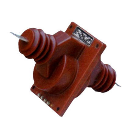
Introduction to the LA-10Q Current Transformer
The LA-10Q is a medium-voltage cast-resin current transformer engineered for high-fidelity current measurement and dependable protective relaying in 11kV (IEC-rated) power systems, equivalent to 10kV in domestic applications. Designed for both indoor and outdoor substations, this instrument transformer leverages vacuum pressure impregnation (VPI) epoxy resin technology to encapsulate its magnetic core and windings, delivering superior dielectric strength, mechanical robustness, and environmental resilience compared to traditional oil-filled alternatives.
Operating Principle of Cast-Resin Insulation
Cast-resin insulation in the LA-10Q utilizes a thermosetting epoxy compound that fully encapsulates the primary conductor, secondary windings, and GOES (grain-oriented electrical steel) core under vacuum conditions. This VPI process eliminates air voids and moisture ingress pathways, ensuring uniform electric field distribution and preventing partial discharge even under transient overvoltages. The cured resin exhibits a relative permittivity of approximately 4.5 and volume resistivity exceeding 1×10¹⁴ Ω·cm at 20°C. Unlike oil-immersed CTs, which require periodic oil sampling and sealing integrity checks, the LA-10Q’s solid insulation system is maintenance-free over its operational life, with no risk of leakage or flammability—critical for compliance with NFPA 70E arc flash safety protocols in confined substation spaces.
Advantages Over Oil-Immersed Designs
The LA-10Q’s cast-resin construction offers distinct technical advantages: immunity to thermal expansion-induced pressure build-up, elimination of fire hazards (achieving UL 94 V-0 flammability rating), and resistance to UV degradation when installed outdoors. Its compact footprint reduces spatial requirements in switchgear bays by up to 30% compared to oil-filled units of equivalent rating. Additionally, the absence of liquid insulation simplifies transportation logistics and avoids environmental permitting constraints associated with hydrocarbon-based fluids. Field data from European distribution networks indicate a 40% reduction in lifecycle maintenance costs for cast-resin CTs like the LA-10Q versus oil types over a 25-year service horizon.
Typical Application Overview
The LA-10Q is deployed across utility substations, industrial plants, and renewable energy interconnection points where accurate current transformation is essential for revenue metering (Class 0.2S/0.5S) and fault detection (Class 5P/10P). Common configurations include single-phase pole-mounted installations on 11kV feeders, three-phase assemblies in metal-enclosed switchgear, and retrofit replacements in aging 10kV infrastructure undergoing modernization. Its dual secondary windings support simultaneous connection to metering and protection circuits without cross-interference, enabled by magnetically shielded core segments meeting IEC 61869-2 clause 6.3.2 requirements.
Technical Specifications
The LA-10Q adheres to stringent performance parameters defined by IEC 61869-2 and GB/T 20840.2, ensuring interoperability across global power systems. Key specifications are detailed below:
| Parameter | Value |
|---|---|
| Rated System Voltage (Um) | 12 kV (IEC), 11.5 kV (GB) |
| Primary Current (Ip) | 50–3000 A (standard ratios) |
| Secondary Current (Is) | 1 A or 5 A |
| Accuracy Classes | Metering: 0.2S, 0.5S; Protection: 5P10, 5P20, 10P10 |
| Rated Output (VA) | 5–30 VA per secondary winding |
| Insulation Level (BIL) | 75 kV peak (1.2/50 μs impulse), 28 kV rms (1 min power frequency) |
| Short-Time Thermal Current | 25 kA for 1 s (Ip ≤ 600 A); 31.5 kA for 1 s (Ip > 600 A) |
| Dynamic Withstand Current | 62.5 kA peak |
| Ambient Temperature Range | –25°C to +40°C (indoor/outdoor) |
| Altitude Limit | ≤ 1000 m above sea level (derating required above 1000 m) |
Standard Service Conditions
The LA-10Q is rated for continuous operation under IEC 60060-defined standard atmospheric conditions: ambient temperature between –25°C and +40°C, relative humidity up to 95% non-condensing, and maximum altitude of 1000 m. At altitudes exceeding 1000 m, the power frequency withstand voltage must be derated by 1% per 100 m increment above 1000 m, as per IEC 60071-2. For coastal or industrial environments with high salt fog or chemical contamination, the transformer’s hydrophobic resin surface resists tracking, achieving a creepage distance of ≥20 mm/kV (pollution severity class III per IEC 60815).
Core and Winding Construction
The magnetic circuit employs high-permeability GOES laminations (M4 grade, 0.3 mm thickness) annealed to minimize hysteresis losses (<0.8 W/kg at 1.5 T, 50 Hz). Secondary windings use electrolytic-tough-pitch (ETP) copper with Class F (155°C) enamel insulation, wound directly onto the core leg to reduce leakage reactance. Each winding is individually encapsulated within the resin matrix, with inter-winding insulation thickness ≥3 mm to withstand test voltages per IEC 61869-2 Table 5. Primary conductors are either solid copper bars (for ≤600 A) or hollow aluminum tubes (for >600 A) to optimize thermal dissipation during overload conditions.
Typical Applications
The LA-10Q serves diverse roles in modern power infrastructure, leveraging its dual-secondary architecture and robust insulation for mission-critical functions.
Substation Secondary Metering
In 11kV/0.4kV distribution substations, the LA-10Q provides Class 0.2S accuracy for revenue-grade energy metering at the medium-voltage incomer. Its low phase displacement error (<±10 minutes at 1–120% In) ensures compliance with EN 50470-3 for billing applications. Dual secondaries allow one winding to feed a smart meter while the other connects to a SCADA RTU, eliminating the need for external test switches. In urban substations with space constraints, the LA-10Q’s compact dimensions (height: 380 mm, diameter: 180 mm) enable retrofit into legacy switchgear originally designed for oil CTs.
Industrial Power Distribution
Heavy industries such as steel mills and petrochemical plants deploy LA-10Q units on 11kV motor feeder circuits to supply inputs to multifunction relays (e.g., SEL-751). Here, the 5P20 protection class ensures linear response up to 20× rated current during motor inrush or short-circuit events. The transformer’s high dynamic withstand (62.5 kA peak) accommodates fault currents from large upstream generators. Grounding of the resin housing via the M10 stud terminal mitigates induced voltages in adjacent control cables, critical in EMI-sensitive environments.
Renewable Energy Integration
Solar PV and wind farms utilize LA-10Q CTs at the point of interconnection (POI) to grid operators’ 11kV networks. The CT’s low remanence (<10% of saturation flux density after 20× In interruption) prevents core saturation during rapid load rejection events common in inverter-based resources. For anti-islanding protection schemes, the 0.5S metering winding feeds synchrophasor measurements with time synchronization accuracy ≤1 μs, supporting IEEE C37.118.2 compliance.
Rural and Suburban Distribution Networks
In rural electrification projects across Asia and Africa, LA-10Q units are pole-mounted on 11kV overhead lines feeding agricultural loads. Their UV-stabilized resin housing withstands prolonged solar exposure without embrittlement, while the IP54-rated terminal box protects secondary connections from dust and rain. The 10P10 protection class reliably triggers reclosers during tree-contact faults, minimizing outage duration. Domestic 10kV systems benefit from identical physical dimensions, enabling seamless interchangeability.
Compliance with International Standards
The LA-10Q is certified to IEC 61869-2:2012 (Instrument transformers – Part 2: Additional requirements for current transformers) and aligns with China’s GB/T 20840.2-2014, ensuring global acceptance.
IEC 61869-2 Certification Details
Compliance encompasses all clauses of IEC 61869-2, including thermal stability (Clause 5.3), accuracy verification under burden variation (Clause 6.2), and short-circuit performance (Clause 7). Type tests conducted by accredited labs confirm: ratio error ≤±0.2% and phase displacement ≤±10′ for 0.2S class at 100% In; composite error ≤5% for 5P10 at 10× In. The transformer passes the 1.2/50 μs lightning impulse test at 75 kV without flashover, satisfying Clause 8.3. Partial discharge levels remain below 10 pC at 1.2 Um/√3, per Clause 9.2.
Alignment with GB/T 20840.2
While GB/T 20840.2 mirrors IEC 61869-2 structurally, key differences exist: GB requires a higher power frequency test voltage (30 kV rms vs. 28 kV) and mandates additional seismic testing for regions prone to earthquakes (Zone II per GB 50260). The LA-10Q meets these through reinforced core clamping and resin formulation with enhanced damping properties (loss factor tan δ = 0.02 at 50 Hz). Domestic 10kV systems reference GB’s rated voltage of 11.5 kV (vs. IEC’s 12 kV), but the LA-10Q’s insulation design accommodates both without modification.
Testing and Certification Requirements
Each production batch undergoes routine tests per IEC 61869-2 Table 1: power frequency withstand (28 kV rms, 1 min), turns ratio verification (±0.25% tolerance), and polarity check. Type tests—conducted every five years or after design changes—include temperature rise (Δθ ≤ 60 K for windings), short-time current (25 kA/1 s), and impulse withstand. Certificates from SGS or TÜV include traceable calibration data against NIST standards.
On-Site Testing Procedures
Pre-commissioning field tests validate LA-10Q integrity after transport and installation, per IEEE C57.13.6 and IEC 61869-2 Annex D.
Insulation Resistance Test
Using a 2500 V DC megohmmeter, measure insulation resistance between primary-to-ground, secondary-to-ground, and primary-to-secondary. Acceptance criteria: ≥1000 MΩ at 20°C. Correct for temperature using RT = R20 × 2(20–T)/10. Values below 500 MΩ indicate moisture ingress or resin cracking, requiring drying or replacement. Perform before and after power frequency tests to detect insulation degradation.
Turns Ratio Test
Apply 1–5 V AC (50/60 Hz) to the secondary winding and measure induced primary voltage. Calculate ratio as Vp/Vs × Ns. Tolerance: ±0.25% of nominal ratio. For a 600/5 A CT, measured ratio must be 120 ±0.3. Use a dedicated ratio tester (e.g., Omicron CT Analyzer) to avoid burden errors. Verify all tap combinations if multi-ratio.
Polarity Test
Confirm reducing polarity (IEC standard): connect DC source (+) to P1 and (–) to P2; connect galvanometer between S1 and S2. A momentary positive deflection indicates correct polarity. Incorrect wiring causes 180° phase shift, leading to relay misoperation. Document results with timestamped photos for commissioning records.
Power Frequency Withstand Voltage Test
Apply 28 kV rms (50 Hz) between primary and grounded secondary/housing for 1 minute. Monitor for flashover, excessive leakage current (>1 mA), or audible discharge. Use a calibrated test transformer with overcurrent trip set at 50 mA. Conduct only after insulation resistance exceeds 1000 MΩ. For 10kV domestic systems, apply 24 kV rms per GB/T 20840.2.
Short-Circuit Test (CT-Specific)
Inject 10× rated current (e.g., 6000 A for 600/5 A) into the primary for 1 second using a portable current generator. Verify secondary output remains within accuracy class limits (e.g., ≤5% composite error for 5P10). Monitor housing temperature rise—should not exceed 80°C. This validates thermal and electromagnetic integrity under fault conditions.
Preventive Maintenance Guide
Although cast-resin CTs require minimal maintenance, periodic inspections extend service life beyond 30 years.
Annual Visual and Electrical Inspection
Inspect for: resin surface cracks (use UV lamp to detect tracking), terminal corrosion (clean with isopropyl alcohol), and loose hardware (torque M10 studs to 25 N·m). Measure insulation resistance annually; a 30% drop from baseline warrants investigation. Check secondary circuit continuity—open circuits can induce dangerous voltages (>2 kV) during primary energization. Ensure grounding conductor resistance ≤0.1 Ω.
Five-Year Comprehensive Maintenance
Every 60 months, perform: partial discharge measurement (acceptance: <20 pC at 1.2 Um/√3), turns ratio re-verification, and thermal imaging under load (ΔT ≤10°C between phases). Replace silica gel in terminal box desiccant if discolored. Review historical data for trend analysis—increasing ratio error may indicate core degradation.
Maintenance Intervals and Fault Diagnosis
| Interval | Task | Fault Indicator |
|---|---|---|
| Annually | Visual inspection, IR test | Cracks, discoloration, IR <500 MΩ |
| 5 Years | PD test, ratio check | PD >20 pC, ratio error >0.5% |
| After Fault | Dynamic withstand verification | Deformation, abnormal noise |
Common faults include secondary open-circuit (causing core saturation and overheating) and moisture ingress at terminal seals. Diagnose via dissolved gas analysis (DGA) is unnecessary—unlike oil CTs—as resin does not produce fault gases.
Conclusion
The LA-10Q 11kV cast-resin current transformer represents a benchmark in medium-voltage instrumentation, combining IEC 61869-2-certified accuracy with the reliability of solid insulation technology. Its GOES core ensures minimal losses and stable performance across metering (0.2S/0.5S) and protection (5P/10P) applications, while the VPI epoxy resin housing delivers exceptional dielectric strength, environmental resistance, and fire safety. Compliance with both international (IEC) and domestic (GB) standards enables seamless deployment in global substation, industrial, and renewable energy projects. With a design life exceeding 30 years and minimal maintenance requirements—limited to annual visual checks and quinquennial electrical tests—the LA-10Q significantly reduces total cost of ownership compared to oil-immersed alternatives. Its robust short-circuit withstand capability (25–31.5 kA/1 s) and precise ratio stability under transient conditions make it indispensable for modern power systems demanding both operational safety and measurement integrity. Engineers specifying the LA-10Q gain a future-proof solution that meets today’s regulatory requirements while accommodating tomorrow’s grid complexities.
Frequently Asked Questions (FAQ)
Q1: Can the LA-10Q be used on 10kV domestic systems?
Yes. While rated for 11kV (IEC Um = 12 kV), the LA-10Q is fully compatible with 10kV systems (GB Um = 11.5 kV) due to its insulation level (28 kV rms withstand). No derating is required.
Q2: What happens if the secondary circuit is left open?
An open secondary during primary energization induces dangerously high voltages (>2 kV) due to core saturation, risking insulation failure and personnel hazard. Always short-circuit secondary terminals before disconnecting loads. The LA-10Q includes internal shorting links for safety during maintenance.
Q3: How many secondary windings does the LA-10Q support?
Standard models feature two independent secondary windings (e.g., 0.2S for metering + 5P20 for protection). Custom configurations with three windings are available upon request, each with separate terminal blocks.
Q4: Is the LA-10Q suitable for outdoor coastal installations?
Yes. The UV-resistant, hydrophobic resin housing achieves pollution severity class III (creepage ≥20 mm/kV), making it suitable for coastal areas with salt fog. Ensure terminal box gaskets are replaced every 10 years.
Q5: What is the maximum altitude for installation without derating?
The LA-10Q is rated for ≤1000 m altitude. Above 1000 m, reduce the power frequency test voltage by 1% per 100 m increment (e.g., 26.6 kV at 1500 m). Contact the manufacturer for high-altitude certification.