Article Content
Introduction
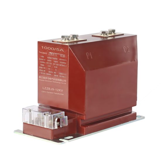
The LZZBJ9-10 current transformer is a high-accuracy, indoor-type instrument transformer designed for use in 10kV AC power systems operating at 50Hz or 60Hz. It serves critical roles in metering, protection, and monitoring applications by accurately stepping down primary currents to standardized secondary values (typically 1A or 5A) suitable for interfacing with relays, meters, and control devices. Manufactured in compliance with IEC 61869 and GB/T 20840 standards, the LZZBJ9-10 features an epoxy resin cast insulation structure that ensures excellent dielectric strength, mechanical robustness, and resistance to environmental stressors such as humidity and pollution. Its compact design facilitates installation in switchgear panels, ring main units (RMUs), and other confined electrical enclosures commonly found in medium-voltage distribution networks.
Proper installation of the LZZBJ9-10 is essential not only for operational accuracy but also for personnel safety and system reliability. Incorrect mounting, inadequate clearances, or improper primary conductor routing can lead to measurement errors, overheating, partial discharge, or even catastrophic failure under fault conditions. This document outlines the foundational requirements that must be verified and implemented prior to energizing the transformer. Adherence to these guidelines ensures optimal performance over the equipment’s service life while maintaining compliance with local electrical codes and utility specifications. The following sections detail pre-installation checks, mechanical mounting criteria, and primary connection protocols necessary for safe and effective deployment of the LZZBJ9-10 in 10kV installations.
Pre-Installation Requirements
Before physically installing the LZZBJ9-10 current transformer, a comprehensive set of verification and preparatory steps must be completed to ensure compatibility, safety, and long-term reliability. These steps encompass documentation review, visual and mechanical inspection, environmental assessment, and coordination with associated system components.
First, confirm that the transformer model matches the project specifications. The LZZBJ9-10 series includes variants with different accuracy classes (e.g., 0.2S for metering, 5P10/5P20 for protection), rated primary currents (e.g., 50A, 100A, up to 3000A), and secondary configurations (single or dual windings). Verify the nameplate data against the single-line diagram and equipment schedule. Additionally, ensure that the transformer’s insulation level (e.g., 12/28/75 kV per IEC 60071) aligns with the system’s maximum operating voltage and impulse withstand requirements.
Conduct a thorough visual inspection upon receipt. Check for cracks, deformations, or surface contamination on the epoxy housing. Inspect terminal studs for damage or corrosion. Confirm that all secondary terminals are properly labeled (e.g., S1, S2, and possibly S3 for dual-ratio models) and protected by insulating caps. Any physical defect must be reported immediately; do not install a damaged unit.
Evaluate the installation environment. The LZZBJ9-10 is rated for indoor use only, with an ambient temperature range typically between -5°C and +40°C. Relative humidity should not exceed 85% without condensation. Ensure adequate ventilation around the transformer to prevent localized heating, especially when installed near high-current busbars or in densely packed switchgear. Avoid locations subject to excessive vibration, chemical fumes, or conductive dust.
Finally, coordinate with adjacent equipment. Verify that the switchgear or panel cutout dimensions accommodate the transformer’s outline and mounting flange. Confirm that primary conductors (busbars or cables) can pass cleanly through the central window without forcing or bending. Secondary wiring routes must allow for strain relief and separation from high-voltage circuits to minimize electromagnetic interference.
| Pre-Installation Check | Requirement | Verification Method |
|---|---|---|
| Nameplate Data | Matches project specs (ratio, accuracy, insulation level) | Cross-reference with drawings and purchase order |
| Physical Condition | No cracks, chips, or terminal damage | Visual and tactile inspection |
| Ambient Conditions | Indoor, -5°C to +40°C, RH ≤85% | On-site environmental assessment |
| Panel Compatibility | Sufficient cutout size and clearance | Measure panel opening vs. transformer dimensions |
| Secondary Wiring Plan | Dedicated, shielded paths away from HV | Review wiring diagrams and cable routing |
Mechanical Installation Requirements
Mechanical mounting of the LZZBJ9-10 must ensure structural stability, proper alignment, and maintenance of required electrical clearances throughout its operational life. The transformer is typically secured via a rear-mounted flange with four M8 or M10 threaded holes, depending on the specific model variant. Installation must be performed using appropriate hardware and torque specifications to prevent mechanical stress on the brittle epoxy resin housing, which could compromise dielectric integrity.
The mounting surface—usually the rear wall of a switchgear compartment or a dedicated support bracket—must be flat, rigid, and non-magnetic to avoid eddy current losses. Steel panels are acceptable if they are part of the grounded enclosure, but aluminum or stainless steel should be used for custom brackets to minimize magnetic interference. The surface must be clean and free of burrs or protrusions that could create uneven pressure points during bolting.
Use only the manufacturer-recommended fasteners: typically stainless steel bolts, washers, and locknuts or thread-locking compound to prevent loosening due to thermal cycling or vibration. Over-torquing must be strictly avoided; the recommended torque for M8 bolts is 15–20 N·m, and for M10 bolts, 25–30 N·m. A calibrated torque wrench should be employed during installation. Uneven tightening can induce internal stresses in the casting, potentially leading to microcracks that degrade insulation performance over time.
Critical clearances must be maintained between the transformer body and any grounded or live parts. Per IEC 61439 and local switchgear standards, the minimum creepage and clearance distances for 10kV systems are approximately 125 mm in air and 240 mm along surfaces under standard pollution conditions (Pollution Degree 2). Ensure that no metal tools, debris, or stray conductors remain near the transformer after installation. Additionally, maintain a minimum 20 mm gap between the transformer’s side surfaces and adjacent components to allow for thermal expansion and airflow.
When multiple LZZBJ9-10 units are installed in close proximity (e.g., for three-phase systems), they must be aligned so that their primary windows are coaxial. Misalignment forces the primary conductor into a bent or angled path, increasing mechanical stress and potentially distorting the magnetic field, which affects ratio and phase angle accuracy. Use alignment jigs or laser levels during multi-unit installations to guarantee parallelism.
| Parameter | Requirement | Notes |
|---|---|---|
| Mounting Surface | Flat, rigid, non-magnetic (if bracket) | Steel panel acceptable if grounded |
| Bolt Size | M8 or M10 (per model) | Verify with dimensional drawing |
| Torque Spec | M8: 15–20 N·m; M10: 25–30 N·m | Use calibrated torque wrench |
| Air Clearance (to ground) | ≥125 mm | For 10kV, PD2, dry conditions |
| Surface Creepage | ≥240 mm | Along insulation surface |
| Inter-Unit Spacing | ≥20 mm | For thermal and airflow management |
| Alignment Tolerance | ≤1 mm offset over 100 mm length | For multi-phase installations |
Primary Connections
The primary circuit connection for the LZZBJ9-10 is established by routing the system’s main conductor—either a rigid busbar or a flexible cable—through the central aperture of the transformer. Unlike wound-primary CTs, the LZZBJ9-10 is a bar-type (or “window-type”) current transformer, meaning it does not have internal primary windings; instead, the system conductor itself acts as the single-turn primary. This design simplifies installation but imposes strict requirements on conductor geometry, material, and positioning to ensure accurate current transformation and thermal performance.
The conductor must pass centrally through the transformer window without contacting the inner walls. Eccentric placement can cause magnetic flux imbalance, leading to ratio errors and increased phase displacement, particularly at low load currents. For optimal accuracy, the conductor should be perpendicular to the face of the CT and centered within ±2 mm of the geometric center of the aperture. When using rectangular busbars, orient the wide face parallel to the CT’s plane to minimize reluctance and maximize coupling efficiency.
Conductor material must be compatible with the system’s current rating and thermal limits. Copper is preferred due to its high conductivity and mechanical strength, but aluminum may be used if properly sized (typically 1.6× the cross-section of equivalent copper). All conductors must be deburred and smoothed at edges to prevent corona discharge or localized heating. If multiple turns are required (e.g., for very low primary currents), this is not supported by the LZZBJ9-10 design; instead, select a lower-ratio CT model.
Thermal considerations are critical. The primary conductor must be capable of dissipating heat generated by I²R losses without exceeding the transformer’s rated temperature rise (typically ≤55 K above ambient). Ensure that adjacent joints (e.g., bolted connections or cable lugs) are torqued to specification and coated with antioxidant compound (for aluminum) to minimize contact resistance. Avoid sharp bends or kinks within 150 mm of the CT window, as these can concentrate mechanical stress and impede heat transfer.
For cable installations, use single-core, non-armored cables with smooth outer jackets. Armored or multi-core cables must not be used, as their magnetic sheaths or adjacent conductors can distort the magnetic field. The cable must be straight and taut through the window; sagging or looping introduces inductance variations that affect transient response during fault conditions. Secure the cable with non-magnetic clamps at least 200 mm upstream and downstream of the CT to prevent movement under electromagnetic forces during short circuits.
| Aspect | Requirement | Rationale |
|---|---|---|
| Conductor Position | Centered within ±2 mm | Minimizes ratio/phase errors |
| Orientation | Perpendicular to CT face | Ensures uniform flux linkage |
| Material | Copper or properly sized aluminum | Meets current-carrying capacity |
| Surface Finish | Deburred, smooth edges | Prevents corona and hot spots |
| Cable Type | Single-core, non-armored | Avoids magnetic interference |
| Minimum Straight Length | 150 mm before/after window | Reduces mechanical stress |
| Support Clamps | Non-magnetic, ≥200 mm from CT | Restrains movement during faults |
| Multiple Turns | Not permitted | LZZBJ9-10 is single-turn only |
5. Secondary Wiring
Secondary wiring encompasses all low-voltage control, monitoring, protection, and communication circuits associated with electrical power systems. These circuits interface with primary equipment—such as transformers, circuit breakers, and switchgear—but operate at significantly lower voltages (typically 12 VDC to 240 VAC/DC). Proper secondary wiring is critical for reliable system operation, accurate metering, protective relay coordination, and safe human-machine interaction.
The design and installation of secondary wiring must adhere to applicable standards including IEEE C37 series, IEC 61850 (for digital substations), and NFPA 70 (NEC). Key considerations include wire type selection (e.g., twisted pair, shielded cable), segregation from power conductors to minimize electromagnetic interference (EMI), proper grounding of shields, and clear labeling per ANSI/ISA-5.1 or IEC 60617.
Common secondary circuits include:
- Protective relay inputs/outputs
- Control power distribution
- Metering voltage and current circuits
- Alarm and annunciator circuits
- SCADA and communication links
Wiring errors in secondary systems can lead to false tripping, failure to operate during faults, or damage to sensitive electronics. Therefore, meticulous documentation—including wiring diagrams, terminal schedules, and cable routing plans—is essential throughout installation and commissioning.
| Circuit Type | Voltage Range | Typical Cable Type | Shielding Required? | Separation from Power Cables |
|---|---|---|---|---|
| Protective Relaying (Current) | 1–5 A AC | Twisted Pair, Shielded | Yes | ≥300 mm |
| Control Power | 24–125 V DC | Multi-conductor, Unshielded | No | ≥150 mm |
| Metering (Voltage) | 60–120 V AC | Twisted Pair, Shielded | Yes | ≥300 mm |
| Digital Communication (IEC 61850) | 5–24 V DC | Category 6 or Fiber Optic | Yes (for copper) | ≥300 mm |
| Alarm Circuits | 24–48 V DC | Multi-conductor, Unshielded | No | ≥150 mm |
All terminations must be torque-checked per manufacturer specifications, and insulation resistance testing (minimum 1 MΩ at 500 VDC) should be performed before energization. Continuity and polarity verification are mandatory for CT and VT circuits to prevent misoperation of protection schemes.
6. Pre-Energization Testing
Pre-energization testing is a systematic verification process conducted after mechanical and electrical installation but before applying primary power. Its purpose is to confirm that all components function correctly in isolation and as an integrated system, ensuring safety and operational readiness. This phase is governed by standards such as IEEE 43 (insulation testing), IEEE C37.90 (relay testing), and NETA ATS (Acceptance Testing Specifications).
Key activities include insulation resistance testing, continuity checks, relay calibration, control logic validation, and functional simulation of protection schemes. All tests must be documented with pass/fail criteria, test equipment used, environmental conditions, and personnel signatures.
Insulation resistance (IR) testing is performed using a megohmmeter at specified voltages (e.g., 500 VDC for 600 V systems, 1000 VDC for medium-voltage equipment). Minimum acceptable values are typically 1 MΩ per kV of system voltage, though manufacturer data may dictate stricter thresholds.
Relay testing involves injecting simulated fault currents and voltages to verify pickup settings, time delays, and output contacts. Modern digital relays also require firmware version checks and configuration file validation against approved settings sheets.
Control circuit functionality is tested via manual and automatic sequences—e.g., verifying breaker close/open commands, interlocks, and alarm annunciation. For SCADA-integrated systems, point-to-point communication and data mapping must be validated.
| Test Type | Test Equipment | Acceptance Criteria | Frequency |
|---|---|---|---|
| Insulation Resistance | Megohmmeter | ≥1 MΩ/kV; no downward trend | Once per circuit |
| Continuity & Polarity | Low-resistance ohmmeter, CT analyzer | Correct polarity; resistance < 0.1 Ω | Once per CT/VT circuit |
| Protective Relay Calibration | Relay test set (e.g., Omicron, Doble) | Within ±2% of setpoint; correct timing | Per relay |
| Control Logic Verification | Manual switches, HMI simulator | All sequences operate per logic diagram | Per control scheme |
| Ground Resistance | Fall-of-potential tester | ≤5 Ω for substations (per IEEE 80) | Once per grounding grid |
Any deviation from expected results requires root cause analysis and corrective action before proceeding. Test reports must be reviewed and approved by the commissioning engineer and client representative prior to energization.
7. Energization
Energization is the controlled application of primary voltage and current to a newly installed or modified electrical system. It marks the transition from construction to operational status and must be executed under a formal switching order with strict adherence to safety protocols. The sequence typically begins with auxiliary systems (e.g., station service transformers, DC battery chargers) before progressing to main busbars and feeders.
A pre-energization meeting involving operations, maintenance, engineering, and safety personnel is mandatory. The energization plan must specify step-by-step procedures, responsible persons, isolation points, PPE requirements, and emergency shutdown actions. All non-essential personnel must be evacuated from the area, and barriers or warning signs posted.
Initial energization is often performed under no-load conditions to verify voltage presence, phase rotation, and absence of abnormal noise or heating. Voltage measurements are taken at key points (e.g., relay inputs, metering panels) to confirm correct phasing and magnitude. In three-phase systems, phase sequence must match the utility or upstream source to prevent motor damage.
Upon successful no-load verification, incremental loading may be applied while monitoring for thermal stability, harmonic distortion, and protective device behavior. Any unexpected trip or anomaly halts the process until resolved.
Documentation includes timestamped logs of voltage/current readings, breaker statuses, and observations. Final sign-off occurs only after stable operation is confirmed for a defined period (e.g., 24 hours for critical facilities).
8. Safety
Safety is paramount throughout secondary wiring, testing, and energization activities. Compliance with OSHA regulations, NFPA 70E (Standard for Electrical Safety in the Workplace), and company-specific safety management systems is non-negotiable. All personnel must be qualified for the tasks assigned and wear appropriate personal protective equipment (PPE) based on the arc flash risk assessment.
An up-to-date arc flash study must be available, with labels affixed to all equipment indicating incident energy, arc flash boundary, and required PPE category. During pre-energization testing, circuits are presumed de-energized but treated as live until proven otherwise using the “live-dead-live” verification method with a properly rated voltage detector.
Lockout/Tagout (LOTO) procedures per OSHA 1910.147 must be rigorously followed during any work on electrical systems. Only one person should hold the key to a lock, and group LOTO requires a designated supervisor.
During energization, a dedicated safety observer should monitor the area for unauthorized entry. Emergency response plans—including location of first aid kits, eyewash stations, and fire extinguishers—must be communicated to all team members. Radios or hand signals should be used for communication to avoid misinterpretation.
Finally, all safety-related documentation—permits, risk assessments, training records, and incident reports—must be maintained for audit purposes. Continuous safety culture, reinforced through toolbox talks and near-miss reporting, ensures long-term protection of personnel and assets.