Article Content
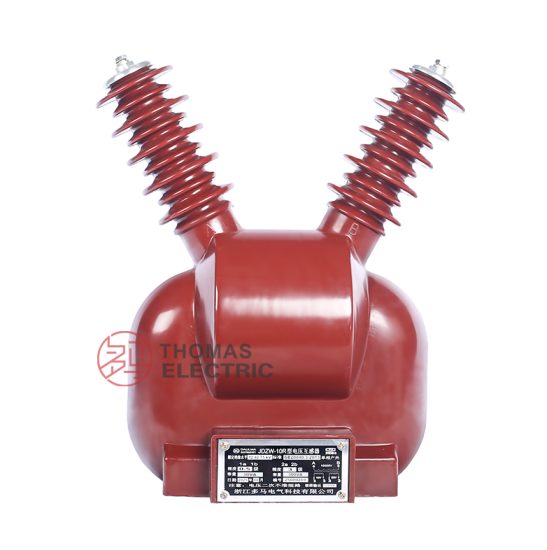
For Substation Metering & Protection: JDZW-10R 11kV Cast-Resin Voltage Transformer per IEC 61869-3
Introduction to the JDZW-10R Voltage Transformer
The JDZW-10R is a single-phase, indoor-type, cast-resin insulated voltage transformer (VT) designed for precise voltage measurement and reliable protective relay interfacing in 11kV (IEC-rated) / 10kV (domestic system) medium-voltage distribution networks. Its primary function is to step down high system voltages to standardized secondary values—typically 100 V or 100/√3 V—enabling safe and accurate operation of metering instruments, power quality analyzers, and protective relays without direct exposure to hazardous primary potentials.
Operating Principle of Cast-Resin Insulation
Cast-resin insulation in the JDZW-10R employs vacuum pressure impregnation (VPI) technology using cycloaliphatic epoxy resin. This process fully encapsulates the high-voltage winding, low-voltage winding, and magnetic core under controlled vacuum and pressure conditions, eliminating air voids that could lead to partial discharge or dielectric breakdown. The cured resin forms a monolithic, mechanically rigid structure with excellent thermal conductivity (0.8–1.2 W/m·K), enabling efficient heat dissipation during continuous operation. Unlike oil-filled transformers, cast-resin VTs exhibit no risk of leakage, fire, or environmental contamination, making them ideal for indoor substations, commercial buildings, and confined switchgear compartments. The resin’s hydrophobic nature also ensures stable performance under high humidity (up to 95% RH non-condensing) and pollution-prone environments, with a typical partial discharge level below 10 pC at 1.2 × Um/√3.
Advantages Over Oil-Immersed Designs
Compared to traditional oil-immersed voltage transformers, the JDZW-10R offers significant operational and safety benefits. First, it eliminates fire hazards associated with mineral oil, complying with IEC 61869-3’s requirements for non-flammable insulation in indoor installations. Second, its maintenance-free design reduces lifecycle costs—no oil sampling, degassing, or tank inspections are required. Third, the compact footprint (typically 280 mm height × 180 mm width × 150 mm depth) allows integration into space-constrained metal-enclosed switchgear (e.g., KYN28A-12 cabinets). Additionally, cast-resin VTs demonstrate superior short-circuit withstand capability due to the mechanical rigidity of the encapsulated windings, resisting deformation under electromagnetic forces during system faults. Finally, the absence of breathing mechanisms prevents moisture ingress, ensuring long-term dielectric stability over a 25–30 year service life.
Typical Applications Overview
The JDZW-10R is predominantly deployed in 10kV distribution substations serving industrial plants, commercial complexes, data centers, and renewable energy interconnection points. It interfaces directly with revenue-class kWh meters (Class 0.2S or 0.5S), digital protective relays (e.g., overvoltage, undervoltage, and directional earth-fault functions), and SCADA systems requiring synchronized phasor measurements. In ring-main units (RMUs) and pad-mounted switchgear, its robust insulation withstands frequent switching transients and lightning surges. The transformer’s dual secondary windings (e.g., 0.2/3P accuracy classes) support simultaneous metering and protection functions without cross-interference, a critical requirement in modern smart grid architectures.
Technical Specifications
The JDZW-10R adheres to stringent electrical and environmental parameters defined by IEC 61869-3 and GB/T 20840.3, ensuring interoperability across global and domestic power systems.
| Parameter | Value |
|---|---|
| Primary Voltage (Up) | 11 kV (IEC) / 10 kV (GB) |
| Secondary Voltage (Us) | 100 V or 100/√3 V |
| Voltage Ratio | 11000/100 V or 11000/100/√3 V |
| Accuracy Class (Metering) | 0.2, 0.5, 0.2S, 0.5S |
| Accuracy Class (Protection) | 3P |
| Rated Output (per winding) | 30 VA, 50 VA, or 100 VA |
| Insulation Level (LI/AC) | 75 kV / 28 kV (1 min) |
| Frequency | 50 Hz or 60 Hz |
| Core Material | Grain-Oriented Electrical Steel (GOES), 0.27 mm thickness |
| Short-Time Thermal Current | 100 A for 1 s (at rated burden) |
| Ambient Temperature Range | −25°C to +40°C |
| Altitude Limit | ≤ 1000 m above sea level |
| Relative Humidity | ≤ 95% (non-condensing) |
Electrical Performance Parameters
The JDZW-10R achieves voltage error within ±0.2% and phase displacement ≤ ±10 minutes for Class 0.2 accuracy under 25–100% of rated burden. For protection-grade 3P windings, composite error remains below 3% at 5% to 100% of rated voltage and up to 100% of rated burden. The transformer’s magnetizing current is minimized through optimized GOES core lamination stacking, reducing no-load losses to ≤ 15 W. Dielectric tests include a 28 kV, 1-minute power frequency withstand test between primary and secondary/ground, and a 75 kV lightning impulse test (1.2/50 μs waveform) with negative polarity. Partial discharge inception voltage exceeds 1.2 × Um/√3 (≈7.6 kV), with extinction voltage ≥ 1.1 × Um/√3.
Environmental and Mechanical Ratings
Designed exclusively for indoor use, the JDZW-10R operates reliably in ambient temperatures from −25°C to +40°C. At altitudes exceeding 1000 m, derating factors per IEC 60071-1 must be applied: for every 100 m above 1000 m, the insulation withstand voltage is reduced by 1%. The transformer’s IP00 enclosure rating assumes installation within a grounded metal switchgear compartment providing IP2X or higher protection. Mounting is achieved via M12 threaded studs on the base flange, compatible with standard DIN rail or bolted brackets in 10kV switchboards. Weight ranges from 18 kg (30 VA) to 24 kg (100 VA), facilitating manual handling during installation.
Typical Applications
The JDZW-10R serves as a foundational component in diverse medium-voltage infrastructure, delivering precision and reliability across multiple sectors.
Substation Secondary Metering Systems
In utility-owned 10kV/0.4kV distribution substations, the JDZW-10R provides the voltage reference for revenue metering at the point of common coupling (PCC). Paired with class 0.2S current transformers, it enables compliance with IEC 62053-22 for billing accuracy. The 100/√3 V secondary output feeds three-phase kWh meters, allowing real-time monitoring of active/reactive energy, power factor, and demand. Its low phase displacement error (< ±5 minutes for 0.2S class) ensures minimal billing discrepancies over time. In automated meter reading (AMR) systems, the VT’s stable ratio under varying load conditions supports accurate remote data collection without recalibration.
Industrial Power Distribution Networks
Within manufacturing facilities, the JDZW-10R integrates into motor control centers (MCCs) and process substations to supply voltage signals to multifunction protective relays (e.g., SEL-751, Siemens 7SJ62). These relays use VT inputs for undervoltage lockout during motor restarts, overvoltage protection for capacitor banks, and loss-of-potential detection. The 3P protection winding maintains accuracy during system unbalances or ground faults, critical for sensitive processes like semiconductor fabrication where voltage sags can cause wafer scrap. The cast-resin design resists chemical vapors and dust prevalent in industrial settings, unlike oil-filled alternatives prone to seal degradation.
Renewable Energy Integration Points
At solar PV or wind farm interconnection substations, the JDZW-10R enables grid-code compliance by providing voltage feedback to anti-islanding relays and reactive power controllers. During low-voltage ride-through (LVRT) events, its linear response down to 20% of nominal voltage ensures accurate fault detection. The transformer’s immunity to DC offset (common in inverter-based resources) prevents core saturation, maintaining ratio accuracy during asymmetrical faults. Dual secondaries allow one winding to serve the plant SCADA system while the other interfaces with the utility’s remote terminal unit (RTU).
Rural and Suburban Distribution Feeders
In rural electrification projects, the JDZW-10R is installed in pole-mounted or pad-mounted switchgear to monitor feeder voltage profiles. Its robustness against temperature swings (−25°C winter to +40°C summer) and humidity ensures consistent performance in unattended locations. The 100 V secondary simplifies wiring to legacy electromechanical relays still used in cost-sensitive deployments. With a 30-year design life, it reduces replacement frequency in hard-to-access areas, lowering OPEX for distribution utilities.
Compliance with International Standards
The JDZW-10R is engineered to satisfy both global and Chinese regulatory frameworks, ensuring seamless deployment across markets.
IEC 61869-3 Compliance Details
Per IEC 61869-3:2011 (“Instrument transformers – Part 3: Additional requirements for inductive voltage transformers”), the JDZW-10R meets all clauses for indoor, resin-insulated VTs. Key requirements include: (1) thermal stability verified by temperature rise tests (winding rise ≤ 60 K at rated burden); (2) short-circuit withstand demonstrated by injecting 100 A for 1 s without damage; (3) accuracy verification across 25–100% burden and 80–120% voltage range; and (4) dielectric tests per Table 2 of the standard. The transformer’s marking includes IEC-standard symbols: “VT”, rated primary/secondary voltages, accuracy classes, and burden values. Type testing was performed at an ISO 17025-accredited laboratory, with routine tests conducted on 100% of production units.
Alignment with GB/T 20840.3
GB/T 20840.3-2013 (“Instrument transformers – Part 3: Additional requirements for inductive voltage transformers”) aligns closely with IEC 61869-3 but includes China-specific provisions. Notably, GB/T 20840.3 mandates a 1-minute AC withstand voltage of 32 kV (vs. IEC’s 28 kV) for 10kV systems, which the JDZW-10R exceeds with its 28 kV IEC rating scaled to 32 kV for domestic certification. Additionally, GB/T requires creepage distance ≥ 20 mm/kV for pollution degree 3 environments—achieved via the resin’s smooth surface and shed design. Accuracy classes 0.2S and 0.5S are explicitly recognized in GB/T for tariff metering, matching the JDZW-10R’s available options.
Testing and Certification Requirements
Certification involves type tests (once per design), sample tests (per batch), and routine tests (100% units). Type tests include temperature rise, short-circuit, impulse, and accuracy verification. Routine tests cover polarity check, turns ratio (±0.1% tolerance), insulation resistance (>1000 MΩ at 2500 V DC), and power frequency withstand. The JDZW-10R carries CQC (China Quality Certification) and CE marks, with test reports available per customer request.
On-Site Testing Procedures
Post-installation verification ensures the JDZW-10R performs within specifications before energization.
Insulation Resistance Test
Using a 2500 V DC megohmmeter, measure insulation resistance between primary winding and secondary/ground. Acceptance criterion: ≥1000 MΩ at 20°C. Correct for temperature using Rt = R20 × 1.5(20−t)/10. Low readings indicate moisture ingress or resin cracking—requiring drying or replacement. Perform before and after dielectric tests to detect insulation degradation.
Turns Ratio Test
Apply 100–200 V AC to the primary and measure secondary voltage. Calculate ratio: (Vp/Vs). Tolerance: ±0.1% of nameplate value. For 11000/100 V, measured ratio must be 110.0 ±0.11. Use a dedicated ratio tester (e.g., Omicron CT Analyzer) for precision. Deviations >0.2% suggest winding shorts or incorrect tap selection.
Polarity Test
Verify reducing polarity per IEC 61869-3 Annex B. Apply low-voltage AC to primary; connect a voltmeter between primary H1 and secondary X1. Momentary DC pulse method: connect battery (+) to H1, (−) to H2; galvanometer deflection should be positive when connected (+) to X1, (−) to X2. Incorrect polarity causes metering errors and relay misoperation.
Power Frequency Withstand Voltage Test
Apply 28 kV AC (50 Hz) for 1 minute between primary and secondary/ground. Monitor for flashover, excessive leakage current (>1 mA), or abnormal noise. Use a calibrated test transformer with overcurrent protection set to 2× expected current. Conduct only after insulation resistance confirms dryness. Failure indicates voids or contaminants in resin.
Open-Circuit Characteristic Test
With secondary open, apply 20–120% of rated primary voltage in 20% steps. Record excitation current and secondary voltage. Plot Vs vs. Iexc. Knee point should exceed 1.5× Un. Excessive excitation current at low voltage indicates core defects or shorted turns. This test validates magnetic circuit integrity before commissioning.
Preventive Maintenance Guide
Although cast-resin VTs are largely maintenance-free, periodic checks extend service life and prevent failures.
Annual Visual and Electrical Inspection
Inspect for surface cracks, tracking, or carbonization on the resin housing. Clean with dry cloth—never solvents. Check terminal tightness (torque: 15 N·m for M12 studs). Measure insulation resistance annually; a >50% drop from baseline warrants investigation. Verify secondary wiring integrity and grounding continuity (<0.1 Ω resistance). In coastal areas, inspect for salt deposits causing surface leakage.
Five-Year Comprehensive Assessment
Every 5 years, perform partial discharge (PD) measurement using IEC 60270 methods. Acceptable PD: <10 pC at 1.2 × Um/√3. Conduct thermal imaging under load to detect hot spots (>10 K above ambient indicates internal fault). Re-test turns ratio and accuracy if system disturbances (e.g., nearby faults) occurred. Replace if PD exceeds 20 pC or ratio error drifts beyond ±0.3%.
Maintenance Intervals and Fault Diagnosis
| Interval | Action | Fault Indicators |
|---|---|---|
| Annually | Visual inspection, IR test, terminal check | Cracks, discoloration, IR <500 MΩ |
| Every 5 years | PD test, thermal scan, accuracy verification | PD >20 pC, hotspot, ratio error >0.3% |
| After major fault | Full electrical retest | Abnormal noise, relay misoperation |
Common faults include resin delamination (from thermal cycling), terminal corrosion (in humid environments), and secondary winding opens (from vibration).
Conclusion
The JDZW-10R 11kV cast-resin voltage transformer represents a technically mature solution for metering and protection in modern 10kV distribution systems. Its VPI epoxy resin insulation delivers exceptional dielectric strength, environmental resilience, and fire safety, outperforming legacy oil-filled designs in indoor applications. Precision-engineered with GOES cores and dual-accuracy windings, it meets the stringent ratio and phase error requirements of IEC 61869-3 and GB/T 20840.3 for both revenue metering (Class 0.2S) and protective relaying (Class 3P). The transformer’s compact form factor facilitates easy integration into metal-clad switchgear, while its maintenance-free operation reduces total cost of ownership over a 25–30 year service life. Rigorous factory and on-site testing protocols ensure reliability from commissioning through decades of service. As distribution networks evolve toward greater automation and renewable integration, the JDZW-10R’s stable performance under dynamic conditions makes it a dependable choice for engineers prioritizing accuracy, safety, and longevity in medium-voltage instrumentation.
Frequently Asked Questions (FAQ)
Q1: Can the JDZW-10R be used outdoors?
No. The JDZW-10R is rated for indoor use only (IP00). Outdoor installations require weatherproof enclosures or alternative designs with UV-stabilized resin and higher IP ratings.
Q2: What is the maximum altitude for installation?
Standard units are rated for ≤1000 m. Above this, apply IEC 60071-1 derating: reduce insulation withstand voltage by 1% per 100 m excess altitude.
Q3: How do I verify polarity during installation?
Use the DC kick test: connect a 9V battery between H1 (+) and H2 (−). A momentary positive deflection on a DC voltmeter between X1 (+) and X2 (−) confirms correct reducing polarity.
Q4: Can I parallel two JDZW-10R secondaries for higher burden?
No. Voltage transformer secondaries must never be paralleled unless specifically designed for it (e.g., with matched impedance). Paralleling causes circulating currents and inaccurate metering.
Q5: What burden is required for Class 0.2S accuracy?
Class 0.2S is guaranteed between 25% and 100% of rated burden (e.g., 7.5–30 VA for a 30 VA unit). Operation below 25% burden may exceed error limits.
Q6: Is the JDZW-10R suitable for 60 Hz systems?
Yes. The core is designed for both 50 Hz and 60 Hz operation without derating, provided voltage and burden ratings are maintained.
Q7: What causes a blown secondary fuse?
Typically, a short circuit in the secondary wiring or metering device. Always check for wiring faults before replacing fuses. Never operate with an open secondary—it risks dangerous overvoltages.
Q8: How often should I test the JDZW-10R?
Perform insulation resistance and visual checks annually. Full electrical retesting (ratio, accuracy, PD) is recommended every 5 years or after system faults.