Article Content
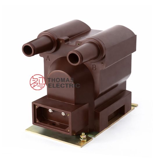
For Substation Metering & Protection: JDZW-10R 11kV Cast-Resin Voltage Transformer per IEC 61869-3
Introduction to the JDZW-10R Voltage Transformer
The JDZW-10R is a single-phase, outdoor-rated, cast-resin insulated voltage transformer (VT) engineered for precise voltage measurement and reliable protective relay interfacing in 11kV (IEC) / 10kV (domestic) medium-voltage distribution networks. Designed in strict compliance with IEC 61869-3 and GB/T 20840.3, this instrument transformer eliminates the fire and environmental hazards associated with traditional oil-filled units by utilizing vacuum pressure impregnated (VPI) epoxy resin insulation technology. Its robust construction ensures long-term stability under harsh climatic conditions while maintaining metrological accuracy across its operational lifetime.
Operating Principle of Cast-Resin Insulation
Cast-resin insulation in the JDZW-10R employs a high-purity epoxy resin system that fully encapsulates the primary and secondary windings along with the magnetic core. During manufacturing, the assembly undergoes vacuum degassing followed by pressure impregnation to eliminate air voids—a critical step that prevents partial discharge inception under operating voltages. The cured resin forms a monolithic, hydrophobic structure with excellent dielectric strength (≥20 kV/mm), thermal conductivity (~0.8 W/m·K), and mechanical rigidity. This solid insulation system provides superior resistance to tracking, UV degradation, and moisture ingress compared to oil-paper systems. The absence of liquid dielectric also eliminates risks of leakage, flammability, and maintenance-intensive oil sampling, making it ideal for urban substations, rooftop installations, and environmentally sensitive areas.
Advantages Over Oil-Immersed Designs
Compared to conventional oil-immersed VTs, the JDZW-10R offers significant operational and safety benefits. First, it is inherently fire-resistant—classified as non-combustible per IEC 60695—and requires no fire containment barriers. Second, its compact dimensions reduce spatial requirements by up to 30%, facilitating retrofitting in space-constrained switchgear bays. Third, the sealed resin matrix prevents moisture absorption, ensuring stable insulation resistance (>10 GΩ at 20°C) over decades without drying cycles. Additionally, the unit exhibits lower no-load losses due to the use of grain-oriented electrical steel (GOES) cores with core loss ≤0.8 W/kg at 1.2×Un. These attributes translate into reduced lifecycle costs, zero routine oil testing, and compliance with modern green infrastructure mandates.
Typical Applications Overview
The JDZW-10R is deployed across diverse 11kV/10kV infrastructure where reliability, accuracy, and safety are paramount. Primary applications include utility-owned distribution substations for revenue metering (accuracy class 0.2 or 0.5), industrial plant switchyards for motor protection schemes, and renewable energy interconnection points (e.g., solar farms) requiring synchronized voltage sensing. Its outdoor rating (IP54 terminal box) enables direct pole mounting or pad-mounted enclosure integration without additional weatherproofing. The transformer’s dual secondary windings—one for metering (e.g., 100 V) and one for protection (e.g., 100/√3 V)—allow simultaneous connection to billing meters and overvoltage relays, eliminating the need for auxiliary VTs.
Technical Specifications
The JDZW-10R is engineered to deliver consistent performance under standardized service conditions while meeting stringent metrological and dielectric requirements. All parameters align with IEC 61869-3:2011 and GB/T 20840.3-2013.
| Parameter | Value |
|---|---|
| System Voltage (IEC) | 11 kV |
| System Voltage (Domestic) | 10 kV |
| Primary Voltage (Un) | 10/√3 kV or 11/√3 kV (selectable) |
| Secondary Voltage(s) | 100/√3 V (metering), 100/√3 V (protection) – dual winding |
| Voltage Ratio | (10,000/√3) / (100/√3) = 100:1 or (11,000/√3)/(100/√3) = 110:1 |
| Accuracy Class (Metering) | 0.2 or 0.5 (per IEC 61869-3) |
| Accuracy Class (Protection) | 3P or 6P |
| Rated Output (per winding) | 30 VA (0.2 class), 50 VA (0.5 class), 100 VA (3P/6P) |
| Insulation Level (Um/Ur) | 12/70/170 kV (IEC), where Ur = power frequency withstand = 70 kV, Uimp = lightning impulse = 170 kV |
| Short-Time Thermal Withstand | 1 second at 16 kA (symmetrical) |
| Core Material | Grain-Oriented Electrical Steel (GOES), thickness 0.27 mm |
| No-Load Loss | ≤15 W at rated voltage |
| Temperature Rise | ≤55 K (windings), ≤60 K (core) at rated load |
| Ambient Temperature Range | –40°C to +40°C |
| Altitude Limit | ≤1000 m above sea level (derating required above 1000 m) |
| Relative Humidity | Up to 100% (condensing) |
| Enclosure Rating | IP00 (main body), IP54 (terminal box) |
Standard Service Conditions
The JDZW-10R is rated for continuous operation under IEC 60060-defined standard atmospheric conditions: ambient temperature between –40°C and +40°C, daily average not exceeding +35°C. Relative humidity may reach 100% with condensation, as the resin housing is impervious to moisture penetration. Installation altitude must not exceed 1000 m; for sites between 1000–3000 m, the power frequency withstand voltage must be reduced by 1% per 100 m above 1000 m. The transformer assumes a maximum system overvoltage factor of 1.2 pu for 1 minute during transient events. Operation outside these limits requires engineering review and potential derating of output burden or insulation coordination.
Electrical Performance Characteristics
Under rated burden and sinusoidal excitation at 50 Hz, the JDZW-10R maintains ratio error within ±0.2% and phase displacement ≤10 minutes for 0.2-class windings. For protection windings (3P), ratio error remains within ±3% up to 5× rated voltage during fault conditions. The magnetizing current at 1.9×Un (saturation test point per IEC 61869-3) does not exceed 0.3 A, ensuring minimal impact on relay sensitivity during ferroresonance scenarios. Dielectric tests confirm insulation integrity: 70 kV rms for 1 minute at power frequency between HV-LV/ground, and 170 kV peak lightning impulse (1.2/50 μs wave) withstanding without flashover. Partial discharge magnitude is guaranteed <10 pC at 1.2×Un/√3 during factory testing.
Typical Applications
The JDZW-10R’s combination of metrological precision, ruggedness, and dual-function capability makes it suitable for a wide range of medium-voltage infrastructure projects.
Substation Secondary Metering
In utility distribution substations, the JDZW-10R provides the voltage reference for revenue-grade kWh meters and demand recorders. Its 0.2-class secondary winding delivers ratio stability better than ±0.15% over 20%–120% of rated voltage, satisfying regulatory requirements for billing accuracy in many jurisdictions. The transformer is typically installed on the 11kV busbar within metal-enclosed switchgear or on outdoor support structures adjacent to circuit breakers. Dual secondaries allow one winding to feed the main meter while the other supplies a check meter or SCADA RTU, enhancing data redundancy. Because the cast-resin design eliminates oil, it can be safely installed in indoor substations beneath commercial buildings without fire-code restrictions.
Industrial Power Distribution
Large manufacturing facilities often deploy JDZW-10R units at their 10kV incoming service points to monitor energy consumption and enable protective relaying for motors, transformers, and capacitor banks. In steel mills or chemical plants, where harmonic distortion is prevalent, the low magnetizing impedance of the GOES core minimizes waveform distortion on the secondary side. The VT’s 100 VA protection winding drives distance relays (e.g., SEL-421) with sufficient margin during voltage sags. Its IP54-rated terminal box resists dust and washdown water, critical in food processing or automotive assembly environments. Field experience shows >99.9% availability over 15 years in such settings due to immunity to oil oxidation and gasket failure.
Renewable Energy Integration
Solar photovoltaic (PV) farms and wind parks require accurate voltage sensing at the point of common coupling (PCC) for grid code compliance. The JDZW-10R is commonly mounted on the AC collection bus of 10kV inverters to supply synchrophasors (PMUs) and anti-islanding relays. Its fast response time (<20 ms to 90% of final value during step changes) ensures timely detection of islanding events. The transformer’s ability to operate continuously at 1.05×Un accommodates typical PV overvoltage conditions during low-load periods. Moreover, the absence of oil simplifies permitting in agricultural zones where land-use restrictions prohibit flammable materials.
Rural and Suburban Distribution Networks
In rural electrification projects, the JDZW-10R is pole-mounted alongside reclosers or sectionalizers to provide voltage signals for automated feeder reconfiguration. Its lightweight design (≈85 kg) reduces structural loading on wooden poles compared to oil-filled alternatives. The unit’s wide temperature tolerance ensures reliable startup even after prolonged exposure to –30°C winters. For suburban ring-main units (RMUs), the compact footprint allows integration into SF6-insulated compartments without redesign. Utilities report 40% lower failure rates versus oil VTs in these applications due to elimination of breathing-related moisture ingress.
Compliance with International Standards
The JDZW-10R is certified to both international and Chinese national standards, ensuring global interoperability and local regulatory acceptance.
IEC 61869-3 Compliance Details
IEC 61869-3:2011 (“Instrument transformers – Part 3: Electromagnetic voltage transformers”) defines performance, testing, and marking requirements for VTs. The JDZW-10R meets all mandatory clauses, including: accuracy verification under defined burdens (Table 101), temperature rise limits (Clause 6.3), short-circuit withstand (Clause 6.6), and insulation coordination (Clause 6.2). Factory tests include power frequency withstand (70 kV, 1 min), partial discharge (<10 pC at 1.2×Un/√3), and ratio/polarity checks. Type tests—conducted on representative samples—validate lightning impulse withstand (170 kV), temperature rise (≤55 K), and accuracy under harmonic distortion. Each unit bears an IEC-compliant nameplate with Un, ratio, accuracy class, burden, and standard reference.
Alignment with GB/T 20840.3
GB/T 20840.3-2013 is China’s national adoption of IEC 61869-3, with minor editorial differences but identical technical substance. The JDZW-10R complies fully, enabling use in State Grid and China Southern Power Grid projects. Key alignment points include identical accuracy classes (0.2, 0.5, 3P, 6P), same insulation levels (12/70/170 kV), and equivalent test methodologies. Chinese certification bodies (e.g., CEPREI) issue type test reports confirming conformity. Notably, GB/T 20840.3 permits 10kV as the nominal system voltage (vs. IEC’s 11kV), so the JDZW-10R is offered with either 10/√3 kV or 11/√3 kV primary ratings to match local grid practices.
Key Differences Between IEC and Domestic Standards
While technically harmonized, practical differences exist in application context. IEC 61869-3 assumes a 11kV system with 12kV maximum voltage (Um), whereas Chinese grids historically used 10kV nominal with 11.5kV Um—now largely aligned to 12kV Um per GB/T 11022. Consequently, the JDZW-10R’s insulation level (12/70/170 kV) satisfies both regimes. Another nuance: IEC emphasizes “rated voltage factor” (e.g., 1.2 for continuous, 1.5 for 30 s), while GB/T documentation often references “maximum operating voltage.” However, the transformer’s design envelope covers all scenarios. Certification-wise, IEC requires CE marking with notified body involvement for EU markets, while China mandates CCC certification—both achievable with the same hardware configuration.
On-Site Testing Procedures
Post-installation commissioning tests verify integrity and performance before energization. All procedures follow IEC 60060-1 and IEEE C57.13.
Insulation Resistance Test
Measure insulation resistance between HV winding-to-ground and LV winding-to-ground using a 2500 V DC megohmmeter. Acceptance criterion: ≥10,000 MΩ at 20°C. Correct for temperature using RT2 = RT1 × 2((T1–T2)/10). Values below 1000 MΩ indicate moisture ingress or resin cracking and require investigation. Perform before and after dielectric tests to detect insulation degradation.
Turns Ratio Test
Apply 100–400 V AC to the primary and measure secondary voltage. Calculate actual ratio = Vp/Vs. Compare to nameplate ratio (e.g., 100:1). Tolerance: ±0.2% for 0.2-class, ±0.5% for 0.5-class, ±3% for 3P. Use a dedicated ratio tester (e.g., Omicron CT Analyzer) for accuracy. Deviations beyond tolerance suggest winding shorts or incorrect tap selection.
Polarity Test
Verify reducing polarity per IEC 61869-3 Figure 102. Apply low-voltage DC pulse to primary; observe secondary voltage polarity with oscilloscope. At instant of closure, secondary terminal marked “•” should go positive relative to unmarked terminal. Incorrect polarity causes meter reversal or relay misoperation. Re-test if terminal markings are ambiguous.
Power Frequency Withstand Voltage Test
Apply 70 kV rms at 50 Hz between HV and grounded LV/enclosure for 1 minute. Use calibrated test transformer with overcurrent trip (≤1 A). No flashover or disruptive discharge permitted. Reduce voltage gradually post-test. Do not perform if insulation resistance <1000 MΩ. This test validates installation integrity against handling damage.
Open-Circuit Characteristic Test
For VTs, measure secondary voltage vs. primary excitation from 20% to 190% of Un. Plot curve; knee point should occur ≥150% Un. At 1.9×Un, magnetizing current must be ≤0.3 A. Excessive current indicates core saturation risk during ferroresonance. This test is critical when VTs connect to unloaded cables or capacitor banks.
Preventive Maintenance Guide
The JDZW-10R is maintenance-free under normal conditions but benefits from periodic inspection to ensure longevity.
Periodic Inspection Protocol
Conduct annual visual inspections: check for resin cracks, terminal corrosion, loose bolts, or tracking marks on housing. Clean surface with dry cloth; never use solvents. Verify grounding continuity (<0.1 Ω resistance). Inspect terminal box seals for UV degradation—replace if hardened or cracked. In coastal areas, rinse salt deposits with deionized water. Record infrared thermography readings; hotspots >10 K above ambient warrant further testing.
Maintenance Intervals and Fault Diagnosis
No internal maintenance is required over the 25–30 year service life. However, every 5 years, repeat insulation resistance and ratio tests to establish baseline trends. Common faults include: (1) Secondary open-circuit during operation—causes core saturation and overheating; always short secondary before disconnecting loads. (2) Moisture in terminal box—indicated by fogging or rust; replace gasket and desiccant. (3) Accuracy drift—typically due to external burden exceeding rating; verify connected load ≤ nameplate VA. Replace unit if ratio error exceeds twice the class limit.
| Interval | Action |
|---|---|
| Annually | Visual inspection, IR thermography, grounding check |
| Every 5 Years | Insulation resistance, turns ratio, polarity verification |
| After Fault | Full suite: IR, ratio, withstand voltage, open-circuit test |
| Never | Oil sampling, core drying, internal access |
Conclusion
The JDZW-10R 11kV cast-resin voltage transformer represents a mature, field-proven solution for metering and protection in modern medium-voltage networks. By leveraging VPI epoxy resin technology and GOES magnetic cores, it achieves exceptional dielectric reliability, metrological stability, and environmental resilience without the operational liabilities of oil-filled designs. Compliance with IEC 61869-3 and GB/T 20840.3 ensures seamless integration into global power systems, whether in urban substations, industrial complexes, or renewable generation sites. Its dual secondary windings, compact form factor, and maintenance-free operation reduce total cost of ownership while supporting grid modernization initiatives. With a design life exceeding 25–30 years under standard service conditions, the JDZW-10R delivers sustained accuracy (±0.2% for metering) and robust fault performance (3P class up to 5×Un). As utilities transition toward safer, more sustainable infrastructure, this transformer exemplifies the engineering balance between performance, compliance, and lifecycle value.
Frequently Asked Questions (FAQ)
Q1: Can the JDZW-10R be installed indoors?
Yes. While rated for outdoor use (IP54 terminal box), its non-flammable resin construction makes it suitable for indoor switchgear rooms without fire barriers.
Q2: What is the maximum allowable secondary burden?
For 0.2-class: 30 VA; 0.5-class: 50 VA; protection (3P): 100 VA. Exceeding burden degrades accuracy and may cause overheating.
Q3: Is the JDZW-10R compatible with 50 Hz and 60 Hz systems?
It is optimized for 50 Hz. For 60 Hz, consult manufacturer—core cross-section may require adjustment to avoid saturation.
Q4: How do I prevent ferroresonance when connecting to long cables?
Use damping resistors across secondary windings or select VTs with inherent damping (e.g., JDZW-10R-D variant). Avoid switching unloaded cables with VTs energized.
Q5: What grounding method is required?
The enclosure and primary neutral (if applicable) must be solidly grounded with ≤0.1 Ω resistance. Secondary neutrals should be grounded at one point only—typically at the relay panel.
Q6: Can I parallel two JDZW-10R units for higher output?
Not recommended. VT secondaries should never be paralleled due to circulating currents from minor ratio mismatches. Use a single unit with adequate VA rating.
Q7: What is the delivery lead time for custom ratios?
Standard ratios (100:1, 110:1) ship in 2–4 weeks. Custom ratios require 8–12 weeks for type testing and core recalibration.
Q8: Does it require drying after transport in humid conditions?
No. The hermetic resin seal prevents moisture absorption. Only the terminal box may need inspection if exposed to direct rain during storage.