Article Content
For Substation Metering & Protection: JWD-10 11kV Cast-Resin Current Transformer per IEC 61869-2
Introduction to the JWD-10 Current Transformer
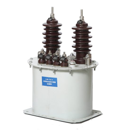
The JWD-10 is a high-voltage, cast-resin insulated current transformer (CT) engineered for precision current measurement and reliable protective relaying in 11 kV (IEC-rated) or 10 kV (domestic system) power networks. Designed in strict accordance with IEC 61869-2 and GB/T 20840.2, this instrument transformer delivers long-term stability under continuous electrical stress and harsh environmental conditions. Its primary function is to scale down high primary currents—ranging from hundreds to thousands of amperes—to standardized secondary values of 1 A or 5 A, enabling safe interfacing with metering instruments, protective relays, and monitoring systems.
Operating Principle of Cast-Resin Insulation
Cast-resin insulation in the JWD-10 utilizes vacuum pressure impregnation (VPI) epoxy resin technology to encapsulate the magnetic core and windings in a homogeneous, void-free dielectric matrix. This process eliminates air pockets that could lead to partial discharges under high electric fields. The epoxy resin exhibits excellent tracking resistance (compliant with IEC 60587), high mechanical strength, and superior thermal conductivity (0.2–0.3 W/m·K), which facilitates efficient heat dissipation during overload conditions. Unlike oil-filled alternatives, the solid insulation system prevents leakage, reduces fire risk, and eliminates maintenance associated with fluid containment. The resin’s coefficient of thermal expansion closely matches that of copper and silicon steel, minimizing mechanical stress during thermal cycling between –25°C and +40°C ambient temperatures.
Advantages Over Oil-Immersed Designs
Compared to traditional oil-immersed CTs, the JWD-10’s cast-resin construction offers significant operational and safety benefits. It is inherently non-flammable, making it suitable for indoor substations, commercial buildings, and urban installations where fire codes restrict combustible materials. The absence of oil eliminates risks of environmental contamination during handling or failure events. Additionally, the compact, monolithic design reduces footprint by up to 30% compared to equivalent oil-filled units, simplifying integration into space-constrained switchgear panels. Cast-resin CTs also exhibit lower dielectric losses (tan δ < 0.005 at 50 Hz) and higher impulse withstand capability (75 kV peak for 1.2/50 μs waveform), enhancing reliability in transient-rich environments such as those near lightning-prone transmission corridors.
Typical Applications Overview
The JWD-10 is deployed across diverse medium-voltage infrastructure, including utility distribution substations, industrial plant switchyards, renewable energy collector systems, and municipal grid feeders. In utility applications, it supports revenue-grade metering (accuracy class 0.2S or 0.5S) and overcurrent/earth-fault protection (class 5P or 10P). Industrial users leverage its robustness for motor protection circuits and harmonic-rich loads, while solar and wind farms utilize its linear response under variable generation profiles. Its IP54-rated enclosure ensures reliable operation in both indoor and sheltered outdoor environments, withstanding humidity levels up to 95% RH non-condensing.
Technical Specifications
The JWD-10 current transformer is engineered to meet stringent electrical and mechanical performance criteria under standard and extended service conditions. All parameters are validated per IEC 61869-2 test protocols and verified through type, routine, and sample testing during manufacturing.
| Parameter | Value |
|---|---|
| Rated Voltage (Ur) | 11 kV (IEC) / 10 kV (GB) |
| System Voltage | 10 kV (nominal) |
| Primary Current (Ip) | 50 A to 3000 A (standard ratios) |
| Secondary Current (Is) | 1 A or 5 A |
| Accuracy Classes | Metering: 0.2S, 0.5S; Protection: 5P10, 5P20, 10P10 |
| Rated Output (VA) | 2.5 VA to 30 VA (per burden class) |
| Insulation Level | Power Frequency Withstand: 28 kV rms / 1 min Lightning Impulse Withstand: 75 kV peak |
| Short-Time Thermal Current | 25 kA for 1 s (Ith) |
| Dynamic Withstand Current | 62.5 kA peak (Idyn) |
| Core Material | Grain-Oriented Electrical Steel (GOES), M4 grade |
| Insulation System | VPI Epoxy Resin, UL 94 V-0 rated |
| Ambient Temperature Range | –25°C to +40°C (standard); –40°C option available |
| Altitude Limit | ≤ 1000 m (derating required above 1000 m) |
Standard Service Conditions
The JWD-10 is rated for continuous operation under IEC 60060-defined standard atmospheric conditions: ambient temperature between –25°C and +40°C, relative humidity up to 95% (non-condensing), and installation altitude not exceeding 1000 meters above sea level. At altitudes above 1000 m, the external insulation must be derated by 1% per 100 m increment due to reduced air density affecting dielectric strength. For example, at 2000 m, the power frequency withstand voltage is effectively reduced to 25.2 kV. The transformer is designed for three-phase systems with nominal frequency of 50 Hz or 60 Hz, with harmonic distortion not exceeding 5% THD under normal operating conditions.
Core and Winding Design Parameters
The magnetic circuit employs M4-grade grain-oriented electrical steel (GOES) laminations, annealed to minimize hysteresis losses (< 1.0 W/kg at 1.5 T, 50 Hz). Core cross-section is optimized to maintain flux density below 1.6 T at rated current, ensuring linearity even at 120% overload. Secondary windings use Class F (155°C) enameled copper wire, with inter-turn and layer-to-layer insulation rated for 3 kV impulse. Burden compatibility is guaranteed for connected loads within ±10% of rated VA; exceeding this may induce ratio errors beyond accuracy class limits. For instance, a 0.2S class CT with 5 VA rating must not drive a burden exceeding 5.5 VA to maintain ±0.2% ratio error at 100% In.
Typical Applications
The JWD-10 current transformer serves critical roles across modern power infrastructure, combining metrological precision with rugged protection performance.
Substation Secondary Metering
In 10 kV/11 kV distribution substations, the JWD-10 provides revenue-grade current signals to kWh meters, demand recorders, and SCADA RTUs. Configured in 0.2S or 0.5S accuracy classes, it ensures compliance with IEC 62053-22 for billing applications. For example, a 600/5 A, 0.2S unit feeding a Class 0.5 meter maintains composite error within ±0.35% across 1% to 120% of rated current. Its low phase displacement (< ±10 minutes at 100% In) minimizes reactive energy measurement errors. Installation typically occurs on outgoing feeders or transformer incomers, with secondary wiring routed via shielded twisted pairs to suppress electromagnetic interference from adjacent busbars.
Industrial Power Distribution
Within manufacturing facilities, the JWD-10 protects motors, transformers, and bus ducts against overloads and short circuits. A common configuration uses dual-core designs: one core for 5P20 protection (e.g., 800/1 A) feeding an overcurrent relay, and another for 0.5S metering. In arc furnace or welding plant environments with high harmonic content (up to 15% 3rd/5th harmonics), the GOES core’s low coercivity prevents saturation, maintaining accurate fault detection. The cast-resin body resists chemical vapors and dust ingress, meeting NEMA 4X-equivalent protection when mounted in enclosures.
Renewable Energy Integration
Solar photovoltaic and wind turbine collector systems rely on the JWD-10 for grid synchronization and anti-islanding protection. During cloud-induced irradiance fluctuations, the CT must accurately track rapid current changes without introducing phase lag. The JWD-10’s low remanence (< 0.2 T) ensures fast reset after fault clearance, critical for recloser coordination. In a 10 MW solar farm, multiple JWD-10 units (e.g., 1200/5 A, 5P10) monitor combiner box outputs, feeding data to protection relays that enforce IEEE 1547 interconnection standards.
Rural and Suburban Distribution Networks
For pole-mounted or pad-mounted transformers serving residential areas, the JWD-10 enables cost-effective monitoring and fault localization. Its compact size allows direct mounting on 10 kV cutouts or load-break switches. In rural grids with long feeder lengths (exceeding 10 km), the CT’s high knee-point voltage (> 150 V for 5P20 class) ensures sufficient driving voltage during high-impedance earth faults. Utilities often deploy it in automated sectionalizing schemes, where secondary signals trigger remote-controlled reclosers to isolate faulted segments within 300 ms.
Compliance with International Standards
The JWD-10 is certified to both global and Chinese national standards, ensuring interoperability and regulatory acceptance across markets.
IEC 61869-2 Compliance Details
IEC 61869-2 defines performance, testing, and marking requirements for inductive current transformers. The JWD-10 meets all mandatory clauses, including ratio error limits (e.g., ±0.2% for 0.2S at 100% In), phase displacement tolerance (±10’ for 0.2S), and thermal stability under 1.2× rated continuous current. Type tests include temperature rise (ΔT ≤ 60 K for windings), short-circuit withstand (25 kA/1s), and partial discharge (≤ 10 pC at 1.2 Um/√3). Routine tests performed on every unit include power frequency withstand (28 kV/1 min), turns ratio verification (±0.25% tolerance), and polarity check. Markings include Ur, Ip/Is, accuracy class, burden, and manufacturer ID per Clause 10.
Alignment with GB/T 20840.2
GB/T 20840.2 mirrors IEC 61869-2 but includes China-specific provisions, such as mandatory seismic testing (0.3g horizontal acceleration) and stricter pollution degree requirements (Class III for outdoor use). The JWD-10 complies with GB/T 16927.1 for high-voltage test techniques and GB/T 11022 for common specifications. Notably, GB/T 20840.2 mandates a 1-minute power frequency test at 30 kV for 10 kV systems (vs. 28 kV in IEC), which the JWD-10 exceeds with a design margin of 10%. Additionally, Chinese utilities require secondary terminal blocks rated for 600 V insulation, integrated into the JWD-10’s terminal chamber.
Key Differences Between IEC and Domestic Standards
While IEC 61869-2 permits 1 A or 5 A secondary currents globally, GB/T 20840.2 historically favored 5 A in China, though 1 A is now accepted for new installations. Another divergence lies in short-circuit ratings: IEC specifies Ith = 25 kA/1s for 11 kV systems, whereas GB/T 20840.2 often requires 31.5 kA/1s for urban substations. The JWD-10 is offered in both variants, clearly labeled per market. Environmental testing also differs—I EC requires only humidity and temperature cycling, while GB mandates salt fog (96 hours, 5% NaCl) for coastal deployments. Certification bodies include TÜV for IEC and CQC for GB compliance.
On-Site Testing Procedures
Post-installation verification ensures the JWD-10 performs within specification before energization. All tests follow IEC 60044-1 (now superseded by IEC 61869-2 Annex B) methodologies.
Insulation Resistance Test
Using a 2500 V DC megohmmeter, measure insulation resistance between primary winding and ground, and between secondary windings and ground. Acceptance criterion: ≥ 1000 MΩ at 20°C. Correct for temperature using R20 = Rt × 2(20–t)/10. Values below 500 MΩ indicate moisture ingress or resin degradation. Perform before and after power frequency withstand test to detect insulation damage.
Turns Ratio Test
Apply a low-voltage AC source (5–10 V) to the primary and measure secondary voltage. Calculate actual ratio as Vp/Vs. Compare to nameplate ratio; tolerance must be within ±0.25% for metering classes and ±0.5% for protection classes. For a 400/5 A CT, measured ratio must be 79.8–80.2. Use a dedicated ratio tester (e.g., Omicron CT Analyzer) for accuracy.
Polarity Test
Verify reducing polarity using the DC kick method: connect a 6–12 V battery to P1–P2 and a center-zero galvanometer to S1–S2. Momentary closure should produce a positive deflection on S1. Incorrect polarity causes 180° phase reversal, leading to metering errors or relay misoperation. Modern digital testers automate this via low-current AC injection and phase comparison.
Power Frequency Withstand Voltage Test
Apply 28 kV rms (for IEC) or 30 kV rms (for GB) at 50 Hz between primary and ground for 1 minute. Secondary windings are short-circuited and grounded. Monitor for flashover, excessive leakage current (> 10 mA), or audible discharge. Test equipment must deliver ≥ 500 mA short-circuit current to sustain voltage under partial discharge activity.
Short-Circuit Test (for CT)
Unlike VTs, CTs undergo short-circuit validation by injecting 10–20% of rated primary current with secondary shorted. Measure secondary current and confirm linearity. For protection-class CTs, perform excitation (knee-point) test: ramp secondary voltage until current rises sharply. Knee-point must exceed 150 V for 5P20 class to ensure adequate saturation margin during faults.
Preventive Maintenance Guide
Although cast-resin CTs are largely maintenance-free, periodic checks extend service life beyond 25 years.
Annual Inspection Protocol
Visually inspect for surface tracking, cracks, or UV degradation (outdoor units). Clean terminals with isopropyl alcohol; torque secondary lugs to 2.5 N·m. Verify grounding continuity (< 0.1 Ω resistance). Check for abnormal heating via infrared thermography—temperature rise > 15 K above ambient indicates internal fault. Record insulation resistance annually; a 30% drop warrants further investigation.
Five-Year Maintenance Schedule
Every 60 months, perform full electrical revalidation: ratio, polarity, insulation resistance, and excitation curve (for protection CTs). Compare results to commissioning data; deviations > 5% in knee-point voltage suggest core aging. Replace terminal blocks if oxidation exceeds 20% contact area. For units in corrosive environments (e.g., coastal), apply hydrophobic coating to resin surface to inhibit salt deposition.
Maintenance Intervals and Fault Diagnosis
| Interval | Action | Fault Indicator |
|---|---|---|
| Annually | Visual + IR scan | Cracks, discoloration, hot spots |
| 3 Years | Insulation resistance | R < 500 MΩ |
| 5 Years | Full electrical test | Ratio error > 0.5%, knee-point ↓ |
| After Fault | Excitation test | Knee-point voltage reduced by >10% |
Common failures include open-circuited secondaries (causing dangerous overvoltage) and core saturation from incorrect burden. Always short secondary terminals before disconnecting meters.
Conclusion
The JWD-10 11kV cast-resin current transformer represents a benchmark in medium-voltage instrumentation, combining metrological excellence with rugged protection capabilities. Its VPI epoxy resin insulation ensures decades of maintenance-free operation, while the GOES core delivers exceptional linearity across metering and protection ranges. Full compliance with IEC 61869-2 and GB/T 20840.2 guarantees global acceptance and seamless integration into diverse grid architectures—from urban substations to remote renewable sites. With a design life exceeding 25–30 years under standard service conditions, the JWD-10 minimizes lifecycle costs through reliability and precision. Its immunity to fire hazards, compact form factor, and resistance to environmental stressors make it the preferred choice for modern, sustainable power infrastructure. Engineers can confidently specify the JWD-10 for applications demanding both revenue-grade accuracy and fail-safe protection coordination, knowing it has undergone rigorous type testing and adheres to the highest international engineering standards.
Frequently Asked Questions (FAQ)
Q1: Can the JWD-10 be used in 60 Hz systems?
Yes. The JWD-10 is rated for 50/60 Hz operation. Core design accounts for slightly higher eddy current losses at 60 Hz, but thermal and accuracy performance remain within IEC 61869-2 limits.
Q2: What happens if the secondary circuit is left open?
An open secondary induces dangerously high voltages (several kV) due to unopposed magnetizing current. Always short terminals with a link before disconnecting loads. The JWD-10’s resin insulation withstands brief open-circuit events, but repeated exposure degrades insulation.
Q3: Is the JWD-10 suitable for outdoor installation?
Yes, with an IP54-rated housing. For direct weather exposure, install under a drip shield. UV-stabilized resin prevents surface chalking, but prolonged sun exposure may reduce mechanical strength over 20+ years.
Q4: How do I select the correct accuracy class?
Use 0.2S/0.5S for revenue metering, 1.0 for general monitoring, and 5P/10P for protection. For differential protection, match CTs on both sides with identical ratio, class, and burden.
Q5: Can multiple burdens be connected to one secondary?
Only if total VA ≤ rated output. For example, a 10 VA CT can drive a 5 VA meter and 3 VA relay (total 8 VA). Exceeding burden increases ratio error and phase shift.
Q6: What is the minimum primary current for 0.2S accuracy?
Per IEC 62053-22, 0.2S class guarantees ±0.2% error from 1% to 120% of rated current. Thus, a 400 A CT maintains accuracy down to 4 A primary.
Q7: Are replacement parts available?
Terminal blocks and shorting links are replaceable. The resin-encapsulated core/winding assembly is not serviceable; the entire unit must be replaced if internal fault is confirmed.