Article Content
Outdoor/Indoor 11kV Cast-Resin Current Transformer LFS-10 – IEC 61869-2 Compliant
Introduction to the LFS-10 Current Transformer
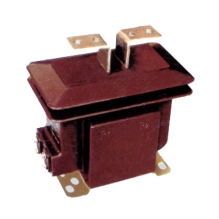
The LFS-10 is a high-voltage, cast-resin insulated current transformer (CT) engineered for precise current measurement and robust protection functions in 11kV (IEC standard) or 10kV (domestic system equivalent) alternating current networks. Designed for both indoor switchgear panels and outdoor pole-mounted or substation applications, this instrument transformer leverages advanced vacuum pressure impregnation (VPI) epoxy resin technology to encapsulate its magnetic core and primary/secondary windings, ensuring long-term dielectric integrity and mechanical stability under harsh environmental conditions.
Operating Principle of Cast-Resin Insulation
Cast-resin insulation in the LFS-10 employs a two-component cycloaliphatic epoxy resin system cured under controlled vacuum and pressure. This VPI process eliminates air voids and moisture ingress pathways, resulting in a homogeneous solid dielectric with high partial discharge inception voltage (>20 kV at 50 Hz). Unlike oil-filled transformers, the solid resin matrix provides inherent fire resistance (compliant with IEC 60695 flammability tests), zero risk of leakage, and immunity to altitude-induced pressure differentials. The resin’s coefficient of thermal expansion closely matches that of copper and silicon steel, minimizing internal stresses during thermal cycling from –40°C to +70°C ambient operation. This design ensures stable dielectric performance over the transformer’s 25–30-year service life without maintenance.
Advantages Over Oil-Immersed Designs
Compared to traditional oil-immersed CTs, the LFS-10 offers significant operational and safety benefits. Its dry-type construction eliminates fire hazards associated with mineral oil, making it suitable for confined indoor spaces such as commercial building substations or underground vaults where fire codes restrict flammable materials. The absence of oil also removes the need for periodic oil sampling, degassing, or tank inspections, reducing lifecycle costs. Furthermore, the compact, lightweight design (typically 15–25 kg depending on ratio) simplifies handling and installation—especially critical in retrofit projects with limited structural support. Environmental compliance is enhanced, as cast-resin units contain no PCBs or hazardous liquids, aligning with RoHS and WEEE directives. Performance-wise, the LFS-10 maintains tighter ratio error tolerances (<±0.2% at 100% rated current for 0.2S class) due to reduced core vibration and consistent magnetic path geometry.
Typical Application Overview
The LFS-10 serves dual roles in power systems: accurate energy metering for billing and revenue-grade applications, and reliable fault current detection for protective relaying. It is commonly deployed in 11kV ring main units (RMUs), pad-mounted transformers, industrial motor control centers, and renewable energy interconnection points (e.g., solar farms feeding into 10/11kV distribution feeders). Its dual-core configuration—often featuring one core optimized for 0.2S/0.5S metering accuracy and another for 5P10/5P20 protection—enables simultaneous connection to revenue meters and overcurrent relays without compromising performance. The transformer’s IP54-rated enclosure (with optional IP65 for outdoor use) ensures reliable operation in dusty or humid environments, including coastal regions with salt-laden atmospheres.
Technical Specifications
The LFS-10 adheres to stringent electrical and mechanical parameters defined by IEC 61869-2 and GB/T 20840.2, ensuring interoperability across global power infrastructure.
| Parameter | Value |
|---|---|
| Rated System Voltage (Ur) | 11 kV (IEC) / 10 kV (Domestic) |
| Rated Insulation Level | 12/28/75 kV (Highest voltage for equipment / Lightning impulse / Power frequency withstand) |
| Primary Current (Ip) | 50 A to 3000 A (standard); up to 4000 A (custom) |
| Secondary Current (Is) | 1 A or 5 A (per IEC 61869-2) |
| Current Ratio | Adjustable via multi-tap secondary (e.g., 600/1, 600/5, 400/1, etc.) |
| Accuracy Classes | Metering: 0.2S, 0.5S; Protection: 5P10, 5P20, 10P10 |
| Rated Output (Burden) | 2.5 VA to 30 VA (at specified accuracy class) |
| Short-Time Thermal Current | 20×Ip for 1 s (e.g., 60 kA for 3000 A primary) |
| Dynamic Withstand Current | 50×Ip peak (e.g., 150 kA peak for 3000 A primary) |
| Ambient Temperature Range | –40°C to +40°C (standard); –25°C to +55°C (extended) |
| Relative Humidity | Up to 95% non-condensing |
| Altitude Limit | ≤1000 m above sea level (derating required >1000 m) |
| Core Material | Grain-Oriented Electrical Steel (GOES), M4 grade, 0.27 mm thickness |
| Insulation System | VPI cycloaliphatic epoxy resin, UL 94 V-0 rated |
Standard Service Conditions
The LFS-10 is rated for continuous operation under IEC 60060-defined standard atmospheric conditions: ambient temperature between –40°C and +40°C, relative humidity ≤95% (non-condensing), and installation altitude not exceeding 1000 meters. At altitudes above 1000 m, the external insulation withstand voltage must be derated by 1% per 100 m increment above 1000 m. For example, at 2000 m, the 75 kV power frequency test voltage becomes 67.5 kV. The transformer’s thermal design accommodates a maximum conductor temperature rise of 60 K above ambient under rated load, verified through IEC 61869-2 thermal stability tests. Humidity resistance is validated via 10-day damp heat testing (IEC 60068-2-78) with no degradation in insulation resistance (>1000 MΩ at 2500 V DC).
Electrical Performance Parameters
Ratio error and phase displacement are tightly controlled per IEC 61869-2 Table 101. For a 0.2S class LFS-10 unit at 100% rated current and 25% rated burden, ratio error must not exceed ±0.2%, and phase displacement ≤±10 minutes. At 120% overload, these limits relax to ±0.35% and ±15 minutes, respectively. Protection-class cores (e.g., 5P20) maintain composite error ≤5% when subjected to 20× rated primary current with rated burden connected. The magnetizing impedance at knee point (typically 1.8–2.2× rated secondary voltage) ensures minimal saturation during high-magnitude faults. Secondary winding resistance is precisely calibrated (±2% tolerance) to match burden calculations in relay coordination studies.
Typical Applications
The LFS-10’s versatility makes it indispensable across diverse power delivery scenarios requiring precision and reliability.
Substation Secondary Metering
In 11kV primary substations, the LFS-10 provides revenue-grade current signals to kWh meters and power quality analyzers. Its 0.2S accuracy class meets EN 50470-3 and IEC 62053-22 requirements for fiscal metering, ensuring billing accuracy within ±0.2% over a 1–120% current range. Dual-ratio taps allow utilities to adapt to seasonal load variations—for instance, switching from 1200/5 A in summer peak to 600/5 A in winter base load—without replacing hardware. The low phase error (<5 minutes at 100% In) prevents reactive energy miscalculation in tariff structures penalizing poor power factor.
Industrial Power Distribution
Within manufacturing facilities, the LFS-10 monitors large motors (e.g., 1 MW induction drives) and furnaces connected to 10kV busbars. Its 5P20 protection core feeds overcurrent and earth-fault relays (e.g., Siemens 7SJ62) with sufficient saturation margin during bolted three-phase faults (up to 30 kA). The cast-resin housing resists chemical vapors from nearby processes, unlike oil-filled alternatives prone to gasket degradation. In arc flash mitigation schemes, the CT’s fast response (<20 ms saturation time at 20× Ip) enables zone-selective interlocking to isolate faults before incident energy exceeds 8 cal/cm².
Renewable Energy Integration
Solar photovoltaic (PV) plants injecting into 11kV grids rely on the LFS-10 for anti-islanding protection and export/import metering. During cloud-induced irradiance fluctuations, the CT’s linear response down to 1% of rated current (per 0.2S class) accurately captures ramp rates for grid code compliance (e.g., IEEE 1547). The outdoor-rated version (IP65) withstands UV exposure and thermal cycling from –30°C night temperatures to +60°C daytime panel heating. In wind farm collector systems, the LFS-10’s high dynamic withstand (50× Ip) survives transformer inrush currents during turbine startup sequences.
Rural and Suburban Distribution Networks
For utility pole-top installations in remote areas, the LFS-10’s maintenance-free design reduces truck rolls. Its compact size fits legacy 10kV cutouts without structural reinforcement. In single-wire earth return (SWER) systems common in Australia and Africa, modified LFS-10 units with grounded primaries provide earth-fault detection sensitivity down to 5 A. The transformer’s hydrophobic resin surface sheds rainwater, preventing flashovers during wet-pollution events—a critical advantage over porcelain-housed CTs in monsoon climates.
Compliance with International Standards
The LFS-10 is certified to IEC 61869-2:2012 (Instrument transformers – Part 2: Additional requirements for current transformers) and harmonized with China’s GB/T 20840.2-2014, ensuring global acceptance.
IEC 61869-2 Compliance Details
IEC 61869-2 mandates rigorous type tests for accuracy, thermal stability, and dielectric strength. The LFS-10 undergoes all required tests: temperature rise (Clause 7.3), short-circuit withstand (Clause 7.4), and accuracy verification across burden ranges (Clause 7.6). Its insulation coordination follows IEC 60071, with a basic lightning impulse level (BIL) of 75 kV and power frequency withstand of 28 kV RMS for 1 minute. Partial discharge measurements per IEC 60270 confirm levels <10 pC at 1.2× Um/√3, well below the 50 pC limit for resin-insulated apparatus. The standard also defines marking requirements—the LFS-10’s nameplate includes Ipn, Isn, accuracy class, burden, and polarity dots per Clause 8.2.
GB/T 20840.2 Alignment and Differences
While GB/T 20840.2 mirrors IEC 61869-2 structurally, key differences exist. Chinese standards require additional seismic testing (horizontal acceleration 0.3g) for transformers installed in earthquake-prone zones like Sichuan. The GB standard also specifies stricter short-time thermal current ratings: 25× Ip for 1 s versus IEC’s 20× Ip. However, accuracy class definitions (0.2S, 5P20) and burden notation (VA) are identical. The LFS-10 achieves dual certification through parallel testing at accredited labs (e.g., KEMA in Netherlands and CESI in China), with test reports traceable to national metrology institutes.
Testing and Certification Requirements
Certification involves routine tests (100% production), type tests (prototype validation), and special tests (customer-requested). Routine tests include power frequency withstand (28 kV for 1 min), winding resistance measurement, and polarity check. Type tests add temperature rise (verified via mutual heating method), short-circuit force withstand (validated by FEM simulation and physical test), and accuracy mapping at 5%, 20%, 100%, and 120% Ip. Special tests may include chopped wave lightning impulse (for GIS applications) or harmonic distortion analysis. All certificates reference the specific IEC 61869-2 clauses satisfied, enabling seamless integration into utility procurement specifications.
On-Site Testing Procedures
Post-installation verification ensures the LFS-10 performs within design tolerances before energization.
Insulation Resistance Test
Measure insulation resistance between primary-to-secondary, primary-to-ground, and secondary-to-ground using a 2500 V DC megohmmeter per IEC 60270. Acceptance criteria: ≥1000 MΩ at 20°C. Correct for temperature using RT2 = RT1 × 2(T1–T2)/10. Values below 500 MΩ indicate moisture ingress or resin cracking, requiring drying or replacement. Perform before and after power frequency withstand tests to detect insulation degradation.
Turns Ratio Test
Apply low-voltage AC (5–10 V) to the secondary winding and measure induced primary voltage. Calculate actual ratio as Vs/Vp. Compare to nameplate ratio; tolerance must be within ±0.2% for 0.2S class. Alternatively, use a dedicated CT analyzer (e.g., Omicron CT Analyzer) injecting 1–5 A into primary and measuring secondary current. Deviations >0.5% suggest winding shorts or incorrect tap selection.
Polarity Test
Verify reducing polarity per IEC 61869-2 Figure 101. Connect a 1.5 V DC battery between P1 (positive) and P2 (negative) on the primary. Momentarily close the circuit while monitoring secondary terminals S1 and S2 with a center-zero galvanometer. A positive kick indicates correct polarity (S1 corresponds to P1). Incorrect polarity causes watt-hour meters to register reverse energy flow and miscoordinates directional relays.
Power Frequency Withstand Voltage Test
Apply 28 kV RMS at 50 Hz between primary and grounded secondary/enclosure for 1 minute per IEC 60060-1. Use a calibrated HV test set with automatic trip at 10 mA leakage current. No flashover or sustained discharge constitutes pass. For field tests, reduce voltage to 80% (22.4 kV) if equipment history is unknown. Always discharge primary capacitance post-test via grounding stick.
Short-Circuit Test (for CT)
Unlike VTs, CTs require short-circuit validation. Inject 10× rated primary current (e.g., 1000 A for 100 A CT) for 1 second while monitoring secondary voltage. Ensure it remains below knee-point voltage (typically <150 V for 5P20 cores). Excessive voltage indicates core saturation, risking relay misoperation. Record thermal image to confirm no hot spots (>10 K above ambient) at terminals or resin surface.
Preventive Maintenance Guide
Although cast-resin CTs are maintenance-free by design, periodic checks extend service life and prevent unexpected failures.
Periodic Inspection Protocol
Conduct visual and thermographic inspections annually. Check for: (1) Resin surface cracks or tracking marks (indicating UV degradation or pollution flashover); (2) Terminal corrosion or loose bolts (torque to 15 N·m for M8 studs); (3) Abnormal heating at connections (>15 K above ambient via IR camera). Clean enclosures with deionized water and non-abrasive cloth—never solvents that attack epoxy. Verify secondary circuits remain shorted when disconnected to prevent dangerous open-circuit voltages.
Maintenance Intervals and Fault Diagnosis
Replace units exhibiting: (1) Insulation resistance <200 MΩ after cleaning/drying; (2) Ratio error drift >0.5% from baseline; (3) Audible humming (sign of loose core laminations). While major overhauls are impractical due to monolithic resin casting, secondary terminal blocks can be replaced if damaged. Below is a recommended schedule:
| Interval | Action |
|---|---|
| Annually | Visual inspection, IR scan, terminal torque check |
| Every 5 Years | Insulation resistance test, ratio verification, burden measurement |
| After Fault Event | Full suite: ratio, polarity, insulation, thermal imaging |
| End of Life (25–30 yrs) | Replace regardless of condition due to resin embrittlement |
Conclusion
The LFS-10 11kV cast-resin current transformer represents a benchmark in reliability, accuracy, and compliance for modern medium-voltage networks. By leveraging VPI epoxy resin encapsulation and GOES magnetic cores, it delivers IEC 61869-2-certified performance across metering (0.2S) and protection (5P20) applications without the fire risk, maintenance burden, or environmental concerns of oil-filled alternatives. Its dual indoor/outdoor rating, compact form factor, and robust short-circuit withstand make it equally suited for urban substations, industrial plants, and remote renewable sites. Rigorous factory testing ensures ratio errors stay within ±0.2% under normal loads, while the 5P-class cores maintain <5% composite error during 20× overcurrent events—critical for selective relay coordination. With a design life of 25–30 years under standard service conditions, the LFS-10 minimizes total cost of ownership through decades of maintenance-free operation. Utilities and engineers specifying this transformer gain not only technical assurance but also future-proof compatibility with evolving grid codes demanding higher measurement fidelity and faster fault response. As distribution networks grow more complex with distributed generation and smart metering, the LFS-10’s proven resilience and precision will remain foundational to safe, efficient power delivery.