Article Content
Introduction to the LZX-10 Current Transformer
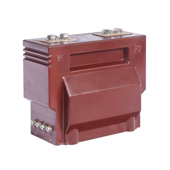
The LZX-10 is a high-reliability, indoor-type cast-resin current transformer (CT) engineered for critical metering and protection functions in 11kV medium-voltage power distribution systems. Designed in strict accordance with IEC 61869-2 and GB/T 20840.2, this device exemplifies modern advancements in solid-insulation instrument transformer technology. Its construction leverages epoxy resin encapsulation with inorganic fillers to achieve superior dielectric strength, mechanical robustness, and environmental resilience—attributes essential for uninterrupted operation in utility substations and industrial switchgear.
Cast-Resin Insulation Technology Principles
Cast-resin insulation involves vacuum pressure impregnation (VPI) or static casting of epoxy-based thermosetting resins around the primary conductor and secondary windings. The LZX-10 employs a cycloaliphatic epoxy system reinforced with silica microfillers, which minimizes thermal expansion mismatch and suppresses partial discharge inception under service voltage stress. This monolithic structure eliminates air voids—a common failure initiation point in oil-paper or gas-insulated alternatives—and provides intrinsic resistance to moisture ingress, tracking, and UV degradation (for indoor applications).
Key Advantages over Oil-Immersed Designs
- Fire Safety: Eliminates flammable insulating oil, meeting stringent fire codes in urban substations and confined switchrooms.
- Maintenance-Free Operation: No need for oil sampling, degassing, or periodic dielectric testing of liquid insulation.
- Environmental Compliance: Avoids PCB contamination risks and simplifies end-of-life disposal.
- Compact Form Factor: Higher dielectric strength of resin enables reduced creepage distances and smaller overall dimensions compared to oil-filled equivalents.
- Vibration Resistance: Rigid encapsulation dampens mechanical resonance, enhancing longevity in high-short-circuit environments.
LZX-10 Specific Innovations
The LZX-10 integrates grain-oriented electrical steel (GOES) cores with precisely controlled magnetic permeability and low hysteresis loss, optimized separately for metering (class 0.2S/0.5S) and protection (5P/10P) windings. Its dual-core architecture allows independent burden management without cross-coupling interference. Additionally, the resin formulation includes hydrophobic additives to mitigate surface condensation in high-humidity environments, while embedded temperature sensors (optional) enable real-time thermal monitoring for predictive maintenance.
Technical Specifications and Design Parameters
The LZX-10 is rated for continuous operation in 50/60 Hz systems with nominal system voltage of 11kV (Um = 12kV). Key design parameters are summarized below:
| Parameter | Value / Range | Standard Reference |
|---|---|---|
| Rated Primary Current (Ip) | 10–4000 A (standard steps) | IEC 61869-2 Table 1 |
| Rated Secondary Current (Is) | 1 A or 5 A | IEC 61869-2 §5.2 |
| Rated Frequency | 50 Hz or 60 Hz | IEC 61869-2 §5.3 |
| Insulation Level (Power Frequency) | 28 kV rms, 1 min | IEC 60071-1 |
| Lightning Impulse Withstand (BIL) | 75 kV peak | IEC 60071-1 |
| Metering Accuracy Class | 0.2S, 0.5S (per IEC 61869-2 Annex B) | IEC 61869-2 §6.3 |
| Protection Accuracy Class | 5P10, 5P20, 10P10, 10P20 | IEC 61869-2 §6.4 |
| Short-Time Thermal Current (Ith) | Up to 40 kA for 1 s (proportional to Ip) | IEC 61869-2 §5.8 |
| Dynamic Withstand Current (Idyn) | 2.5 × Ith | IEC 61869-2 §5.9 |
Accuracy Classes: Metering vs. Protection
Metering windings (0.2S/0.5S) are calibrated for minimal composite error (<±0.2% or <±0.5%) at 1–120% of rated current, ensuring revenue-grade energy measurement even under light-load conditions. In contrast, protection windings (5P/10P) prioritize linearity during fault currents up to 10–20× Ip, with composite error limited to ±5% or ±10% respectively at specified accuracy limit factor (ALF). The “S” suffix denotes special accuracy at low currents (down to 1% Ip), critical for distributed generation interconnection metering.
Thermal and Dynamic Performance
The LZX-10’s thermal design accounts for both steady-state losses (I²R + core losses) and transient short-circuit heating. Temperature rise under rated current is limited to ≤55 K above ambient (40°C), verified via thermal imaging during type tests. Dynamic withstand capability ensures mechanical integrity during asymmetrical fault currents, with core laminations bonded to prevent displacement under Lorentz forces exceeding 100 kN/m².
IEC 61869 Compliance and Standards
Compliance with IEC 61869-2 (“Instrument transformers – Part 2: Additional requirements for current transformers”) forms the foundation of the LZX-10’s design validation. This standard supersedes legacy IEC 60044-1 and introduces harmonized global requirements for performance, safety, and environmental testing.
IEC 61869-2 Specific Requirements
Key mandates include:
- Definition of rated insulation levels per IEC 60071-1
- Mandatory partial discharge (PD) limits: ≤10 pC at 1.2 Um/√3
- Accuracy verification under defined burden conditions (e.g., 2.5 VA for 1 A, 10 VA for 5 A)
- Temperature rise tests under continuous rated current
- Short-circuit withstand verification via thermal and dynamic tests
Testing and Verification Procedures
All LZX-10 units undergo routine tests per IEC 61869-2 §8, including:
- Power frequency withstand test (28 kV, 1 min)
- Partial discharge measurement (≤5 pC typical)
- Winding polarity verification (dot convention)
- Accuracy verification at 5%, 20%, 100%, and 120% Ip
- Insulation resistance (>1000 MΩ at 2500 V DC)
Type tests (conducted on representative samples) further validate BIL, thermal stability, and seismic performance.
Comparison with GB/T 20840 Standards
GB/T 20840.2 (China’s national adoption of IEC 61869-2) aligns closely but includes localized requirements:
- Stricter creepage distance: ≥20 mm/kV for pollution degree III
- Mandatory altitude correction for installations >1000 m
- Additional seismic qualification per GB/T 13540
The LZX-10 meets both frameworks, facilitating deployment in international and domestic Chinese projects.
International Certification Requirements
Certification by accredited bodies (e.g., KEMA, CESI, SGS) confirms compliance. Documentation includes:
- Type Test Report (TTR)
- Routine Test Certificate (RTC)
- Declaration of Conformity (DoC) to IEC 61869-2
- RoHS and REACH compliance statements
These are essential for grid code approval in EU, ASEAN, and Middle Eastern markets.
Installation Guidelines and Best Practices
Proper installation is critical to ensure long-term reliability and measurement integrity.
Site Preparation and Environmental Requirements
The LZX-10 is rated for indoor use only (IP00 enclosure). Ambient conditions must satisfy:
- Temperature: -25°C to +40°C
- Relative humidity: ≤95% (non-condensing)
- Altitude: ≤1000 m (derating required above)
- Pollution degree: II (per IEC 60664-1)
Avoid locations with excessive vibration, corrosive gases, or direct water spray.
Mounting Procedures (Indoor Switchgear)
The transformer features M12 threaded inserts or bolt-through holes for secure panel mounting. Key steps:
- Verify mechanical alignment with busbar or cable termination points.
- Torque mounting bolts to 45 N·m (±5%) using calibrated tools.
- Ensure primary conductor is centered within the aperture to minimize stray flux.
- Maintain minimum clearance of 125 mm to grounded parts (per IEC 61439-2).
For retrofit applications, confirm compatibility with existing busbar dimensions (standard aperture: Ø50 mm).
Electrical Connections and Grounding
Secondary terminals are labeled per IEC 61869-2 (K, L for metering; P1, P2 for protection). Critical practices:
- Use stranded copper conductors (min. 2.5 mm² cross-section).
- Terminate with ring lugs crimped to IEC 61238-1.
- Ground the transformer frame and secondary winding neutral (if applicable) to a single-point earth grid with impedance <0.1 Ω.
- Never leave secondary windings open-circuited during primary energization—use shorting links during maintenance.
Safety Precautions During Installation
Adhere to IEC 61936-1 and local arc-flash protocols:
- De-energize upstream circuit before handling.
- Wear CAT III PPE when working near live parts.
- Verify absence of voltage with a calibrated detector.
- Implement lockout/tagout (LOTO) procedures.
Operation and Performance Characteristics
Load Behavior and Burden Considerations
The total burden (Zb) comprises relay coils, lead resistance, and contact impedance. For 5 A systems, Zb should not exceed the rated burden (e.g., 10 VA = 0.4 Ω). Excessive burden increases ratio error and phase displacement, particularly at low currents. Use the following formula to calculate lead resistance:
Rlead = (ρ × L) / A
Where ρ = resistivity (0.0172 Ω·mm²/m for Cu), L = round-trip length (m), A = conductor area (mm²).
Transient Response Characteristics
During fault inception, DC offset can cause core saturation if the X/R ratio is high. The LZX-10’s gapped protection core (for 5P/10P classes) extends linear range, while metering cores use high-permeability GOES with tight air-gap control to minimize remanence. Transient dimensioning factor (TDF) is typically ≤2.0 for 10P20 ratings.
Temperature Rise and Thermal Management
Heat dissipation occurs via conduction through mounting hardware and convection from the resin surface. In enclosed switchgear, ensure ≥100 cm² ventilation area per CT. Continuous overcurrent (>120% Ip) accelerates aging—monitor via optional embedded Pt100 sensors.
Partial Discharge Performance
Factory-measured PD levels average 3–5 pC at 1.2 Um/√3 (8.3 kV), well below the 10 pC IEC limit. Field PD testing (IEC 60270) is recommended after severe fault events to detect insulation degradation.
Testing Procedures and Quality Assurance
Factory Acceptance Testing (FAT)
FAT includes all routine tests plus customer-specified checks (e.g., burden sweep, harmonic distortion). Witness testing is available for critical projects.
Site Commissioning Tests
Post-installation verification per IEC 60044-6:
- Insulation resistance (≥1000 MΩ)
- Polarity check (using battery-and-galvanometer method)
- Ratio and excitation curve validation
- Burden verification under simulated load
Routine and Type Tests per IEC 61869-2
Routine tests: 100% production.
Type tests: Performed every 5 years or after design changes.
Diagnostic Testing Methods
- Excitation Test: Detects shorted turns by plotting Vsec vs. Iexc.
- Winding Resistance: Measures DC resistance to identify open circuits.
- Capacitance & Tan δ: Assesses bulk insulation condition (though less critical for resin vs. oil).
Maintenance and Troubleshooting
Preventive Maintenance Schedules
Cast-resin CTs require minimal maintenance:
- Visual inspection: Annually (check for cracks, discoloration, dust accumulation)
- Insulation resistance: Every 3–5 years
- Accuracy verification: Every 10 years or after major faults
Common Fault Diagnosis
| Symptom | Possible Cause | Remedial Action |
|---|---|---|
| Inaccurate metering | Excessive burden, core saturation, shorted turns | Check burden, perform excitation test |
| Relay misoperation | Incorrect ALF, polarity reversal | Verify wiring, test ratio under fault simulation |
| Overheating | Loose connections, overcurrent | Tighten terminals, review load profile |
| Cracked housing | Mechanical impact, thermal cycling fatigue | Replace unit—resin cannot be repaired |
Insulation Resistance Testing
Apply 2500 V DC between primary-ground, secondary-ground, and primary-secondary. Record values corrected to 20°C using IEEE 43 factors. A drop >50% from baseline indicates moisture ingress or surface contamination.
When to Replace vs Repair
Cast-resin CTs are non-serviceable. Replace if:
- Insulation resistance <100 MΩ
- Visible cracks or carbon tracking
- Excitation current exceeds 2× baseline at same voltage
- Accuracy error >2× class limit
Application Scenarios and System Integration
Substation Metering Applications
The LZX-10’s 0.2S class supports AMI (Advanced Metering Infrastructure) and fiscal metering at 11kV feeders. Integration with IEC 61850-9-2 LE sampled values enables digital substations.
Protection Relay Coordination
5P20 windings provide reliable input to overcurrent (50/51), earth-fault (50N/51N), and differential relays. Ensure relay burden ≤ CT rated burden to maintain time-current curve accuracy.
Integration with SCADA Systems
Analog outputs (1 A/5 A) interface directly with RTUs. For digital systems, pair with merging units compliant with IEC 61850-9-2.
Case Studies and Field Experience
In a 2023 Guangdong distribution substation upgrade, 24 LZX-10 units replaced oil-filled CTs, reducing footprint by 30% and eliminating annual oil testing. After 18 months, zero failures were recorded despite 12 fault interruptions (max. 28 kA).
FAQ1: Can the LZX-10 be used for both metering and protection simultaneously?
Yes. The LZX-10 features dual independent secondary windings—one optimized for metering (0.2S/0.5S) and another for protection (5P/10P). Each winding has dedicated terminals and burden ratings, preventing interaction between measurement and protection circuits.
FAQ2: What is the maximum altitude rating for the LZX-10?
The standard design is rated for ≤1000 m above sea level. For installations between 1000–2000 m, voltage withstand values must be derated by 1% per 100 m excess altitude per IEC 60071-2. Custom units with enhanced clearances are available for high-altitude sites.
FAQ3: How does cast-resin construction affect partial discharge performance?
Epoxy resin’s high dielectric constant (εr ≈ 3.5–4.0) and absence of gas-filled voids suppress partial discharge inception. The LZX-10 achieves PD levels of 3–5 pC at service voltage—significantly below the 10 pC IEC 61869-2 limit—ensuring decades of insulation life.
FAQ4: Is the LZX-10 suitable for outdoor installation?
No. The LZX-10 is designed exclusively for indoor, clean, dry environments (IP00). For outdoor applications, consider the LZW-10 series with UV-stabilized resin and IP54-rated enclosures.
FAQ5: What happens if the secondary winding is accidentally left open?
An open secondary during primary current flow drives the core into deep saturation, generating hazardous voltages (>10 kV) across the terminals and causing excessive core heating. Always use shorting links during maintenance, and never disconnect secondary leads under load.
FAQ6: How is accuracy verified in the field?
Field accuracy testing uses a portable CT analyzer that injects calibrated primary current (e.g., 10–120% Ip) and measures secondary response against reference standards. Ratio error and phase displacement are compared to class limits per IEC 61869-2 Annex D.