Article Content
11kV Cast-Resin Voltage Transformer RZL-10 for Metering and Protection – IEC 61869-3 Standard
Introduction to the RZL-10 Voltage Transformer
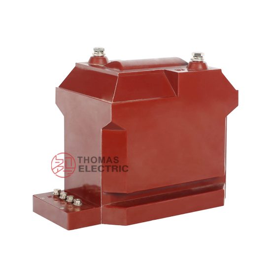
The RZL-10 is a precision-engineered, cast-resin insulated voltage transformer (VT) rated for 11 kV primary system voltage per IEC standards, corresponding to 10 kV nominal in domestic Chinese power networks. Designed for both indoor and outdoor deployment, this instrument transformer provides galvanic isolation and accurate voltage scaling from high-voltage primary circuits to standardized secondary outputs—typically 100 V or 110 V—for use in revenue metering, protective relaying, and power quality monitoring.
Operating Principle of Cast-Resin Insulation
Cast-resin insulation in the RZL-10 employs vacuum pressure impregnation (VPI) of cycloaliphatic epoxy resin around the primary and secondary windings wound on grain-oriented electrical steel (GOES) cores. This process eliminates air voids and moisture ingress pathways, resulting in superior dielectric strength and partial discharge performance. The solid dielectric structure ensures long-term stability under thermal cycling and environmental stress. Unlike oil-filled units, the resin matrix is non-flammable, eliminating fire hazards and simplifying installation in confined or public-access areas. The homogeneous encapsulation also provides mechanical rigidity, reducing vibration-induced winding fatigue and maintaining ratio accuracy over decades of service.
Advantages Over Oil-Immersed Designs
Compared to traditional oil-immersed VTs, the RZL-10 offers significant operational and safety benefits. Its dry-type construction eliminates risks of oil leakage, environmental contamination, and fire propagation—critical in urban substations or industrial facilities with stringent safety codes. Maintenance requirements are drastically reduced; no oil sampling, degassing, or tank inspections are needed. The compact footprint allows integration into space-constrained switchgear panels, while the absence of conservator tanks simplifies mounting geometry. Furthermore, cast-resin units exhibit faster thermal response during transient overvoltages, enhancing coordination with surge arresters. The RZL-10’s design complies with IEC 61869-3’s requirements for pollution degree 3 environments, making it suitable for coastal or industrial atmospheres where salt or chemical deposits could compromise external insulation.
Typical Application Overview
The RZL-10 is deployed across medium-voltage infrastructure where reliability, accuracy, and compliance are non-negotiable. Primary use cases include 10/11 kV distribution substations feeding commercial complexes, manufacturing plants, and municipal utilities. It interfaces directly with digital multifunction meters, distance relays, and synchrophasor measurement units (PMUs). In renewable energy applications, such as solar farms or wind turbine step-up stations, the RZL-10 provides grid-synchronization voltage references. Its robust construction supports operation at altitudes up to 1,000 m without derating, and optional creepage extensions accommodate installations above 2,000 m. The transformer’s low burden requirement (as low as 2.5 VA at 0.5 class) ensures compatibility with modern low-power electronic instrumentation.
Technical Specifications
The RZL-10 adheres to strict dimensional, electrical, and environmental parameters defined by IEC 61869-3 and GB/T 20840.3. Below is a comprehensive specification table followed by detailed subsections.
| Parameter | Value |
|---|---|
| Primary Voltage (IEC) | 11 kV / √3 (phase-to-earth) |
| Primary Voltage (Domestic) | 10 kV / √3 |
| Secondary Voltage | 100 V / √3 or 110 V / √3 (standard); 100 V or 110 V (line-to-line optional) |
| Voltage Ratio | (11,000/√3) : (100/√3) = 110:1 (typical) |
| Accuracy Class | 0.2 / 0.5 / 3P / 6P (per IEC 61869-3) |
| Rated Output | 10–100 VA (depending on accuracy class) |
| Insulation Level (LI/AC) | 75 kV / 28 kV (1.2/50 µs lightning impulse & 1-min power frequency) |
| Partial Discharge | <10 pC at 1.2 × Um/√3 |
| Core Material | Grain-Oriented Electrical Steel (GOES), 0.23 mm thickness |
| Insulation System | Cycloaliphatic epoxy resin, VPI process |
| Ambient Temperature | –25°C to +40°C (standard); –40°C option available |
| Relative Humidity | Up to 95% non-condensing |
| Altitude | ≤1,000 m (standard); derating or extended creepage for >1,000 m |
Electrical Performance Parameters
The RZL-10 achieves ratio error within ±0.2% and phase displacement ≤10 minutes at 0.2 accuracy class under 25–100% of rated burden. For protection-class windings (3P/6P), composite error remains below 3% or 6% respectively at 5× rated voltage. The transformer’s magnetizing current is minimized through optimized GOES core lamination stacking, reducing no-load losses to ≤1.5 W. Thermal stability is ensured by a temperature rise limit of 60 K above ambient for windings under continuous full-load conditions. Short-time thermal withstand capability is 1 second at 100× rated primary voltage without degradation. Burden compatibility extends to inductive, resistive, and mixed loads, with guaranteed performance at power factors between 0.8 lagging and unity.
Environmental and Mechanical Ratings
Designed for harsh service conditions, the RZL-10 features UV-stabilized resin housing suitable for direct sunlight exposure. The creepage distance exceeds 25 mm/kV (minimum 275 mm for 11 kV) to meet pollution degree 3 requirements per IEC 60815. Mounting is via M12 stainless steel bolts with torque specification of 45 N·m; misalignment tolerance is ±2°. The unit weighs approximately 35 kg and measures 380 mm (H) × 220 mm (W) × 180 mm (D). Terminal blocks accept 2.5–16 mm² copper conductors with IP2X finger-safe covers. Optional anti-condensation heaters (24 V AC/DC, 50 W) can be factory-installed for high-humidity environments.
Typical Applications
The RZL-10’s versatility stems from its dual compliance with international and domestic standards, enabling seamless integration across diverse power systems.
Substation Secondary Metering
In 10/11 kV primary substations, the RZL-10 supplies voltage signals to Class 0.2S or 0.5S revenue meters for accurate energy billing. Its low phase error ensures minimal distortion in kWh and kVArh calculations, critical for utility compliance with regulatory accuracy mandates. When paired with class 0.2 CTs, the combined metering chain meets IEC 62053-22 requirements. The VT’s stable ratio over temperature prevents seasonal billing drift—a common issue with lower-grade transformers. In ring-main units (RMUs), the RZL-10’s compact form factor allows side-by-side installation with circuit breakers without panel redesign.
Industrial Power Distribution
Heavy industries such as steel mills, cement plants, and data centers rely on the RZL-10 for motor protection and power quality analysis. Voltage inputs feed into multifunction relays (e.g., Siemens 7SJ, SEL-351) for undervoltage, overvoltage, and loss-of-potential detection. The 3P accuracy class ensures reliable operation during fault conditions when system voltage collapses. In arc-furnace installations, the VT’s immunity to electromagnetic interference (EMI) from harmonic-rich currents maintains signal integrity. Ground-fault detection schemes using residual voltage (3V₀) benefit from the RZL-10’s balanced phase-to-ground transformation characteristics.
Renewable Energy Integration
Solar photovoltaic (PV) plants and wind farms utilize the RZL-10 at the point of interconnection (POI) for grid code compliance. It provides voltage reference for anti-islanding protection, reactive power control (Q(V) curves), and fault ride-through (FRT) logic. The transformer’s fast response time (<20 ms) enables precise synchronization during grid reconnection after outages. In microgrids, the RZL-10 supports droop control algorithms by delivering clean voltage feedback to inverters. Its maintenance-free nature reduces O&M costs in remote renewable sites where access is limited.
Rural and Suburban Distribution Networks
For rural electrification projects, the RZL-10’s outdoor rating and corrosion-resistant hardware ensure decades of service with minimal intervention. Mounted on pole-top platforms or pad-mounted switchgear, it enables remote voltage monitoring via SCADA or IoT sensors. The 6P protection class supports basic overvoltage tripping in cost-sensitive applications. In suburban ring networks, multiple RZL-10 units provide redundancy for critical loads like hospitals or water treatment facilities. The transformer’s ability to operate at 110% continuous overvoltage accommodates daily voltage fluctuations common in lightly loaded rural feeders.
Compliance with International Standards
The RZL-10 is engineered to satisfy both global and regional regulatory frameworks, ensuring interoperability and legal metrology acceptance.
IEC 61869-3 Certification Details
IEC 61869-3 defines performance, testing, and marking requirements for inductive voltage transformers. The RZL-10 undergoes type tests including temperature rise, short-circuit withstand, and accuracy verification across burden and voltage ranges. Routine tests per clause 12 include ratio error, polarity, and power frequency withstand. The nameplate includes mandatory markings: manufacturer, serial number, accuracy class, rated output, frequency (50 Hz), and vector group (typically Yn/yn). Partial discharge levels are measured per IEC 60270 at 1.2 × Um/√3, with acceptance criteria of ≤10 pC. Dielectric tests apply 28 kV RMS for 1 minute between windings and ground, with no flashover or disruptive discharge permitted.
Alignment with GB/T 20840.3
GB/T 20840.3 is China’s national adoption of IEC 61869-3, with minor deviations in test procedures and labeling. Key differences include: (1) GB requires additional seismic testing for transformers used in earthquake-prone zones (Zone 8+ per GB 50260); (2) domestic standards specify 10 kV as nominal system voltage versus IEC’s 11 kV; (3) GB permits slightly wider ratio error tolerances at light loads (e.g., ±0.3% at 20% burden for 0.2 class). The RZL-10 is dual-certified, bearing both CQC and CE marks. Factory test reports include separate columns for IEC and GB compliance, facilitating customs clearance and utility acceptance in both export and domestic markets.
Testing and Certification Requirements
Third-party certification by accredited labs (e.g., KEMA, CESI, or China Electric Power Research Institute) validates compliance. Type tests are valid for five years unless design changes occur. Each production unit undergoes routine tests: visual inspection, winding resistance (±2% tolerance vs. prototype), ratio check (±0.1% deviation allowed), and 3 kV insulation resistance test (>1,000 MΩ minimum). Optional special tests include chopped impulse (for GIS applications) and thermal imaging under load. Documentation includes a Declaration of Conformity referencing IEC 61869-3:2011 and GB/T 20840.3-2017, along with calibrated test certificates traceable to national standards.
On-Site Testing Procedures
Post-installation verification ensures the RZL-10 performs within specifications before energization.
Insulation Resistance Test
Using a 2,500 V DC megohmmeter, measure insulation resistance between primary winding and ground, secondary winding and ground, and inter-winding. Acceptance criteria: ≥1,000 MΩ at 20°C. Correct for temperature using the formula RT2 = RT1 × 2((T1–T2)/10). Low readings indicate moisture ingress or resin cracking—requiring drying or replacement. Perform before and after dielectric tests to detect insulation degradation.
Turns Ratio Test
Apply 100–200 V AC to the primary and measure secondary voltage with a calibrated voltmeter (accuracy class 0.1 or better). Calculate actual ratio and compare to nameplate. Tolerance: ±0.2% for metering class, ±0.5% for protection class. Use a dedicated turns ratio tester (e.g., Omicron CT Analyzer) for automated comparison. Deviations beyond tolerance suggest winding shorts or incorrect tap selection.
Polarity Test
Verify reducing polarity per IEC 61869-3 Figure 3. Connect a 6–12 V battery across primary terminals (H1+, H2–). Momentarily close the circuit while monitoring secondary with a DC voltmeter (X1+, X2–). A positive kick confirms correct polarity. Incorrect polarity causes 180° phase reversal, leading to metering errors or relay misoperation. Document results with oscillograph traces if available.
Power Frequency Withstand Voltage Test
Apply 28 kV RMS at 50 Hz for 1 minute between primary and grounded secondary/core. Use a calibrated HV test set with automatic trip on flashover. Current should remain below 10 mA. Do not perform if moisture is suspected—dry the unit first. This test validates insulation integrity after transport and installation stresses.
Open-Circuit Characteristic Test
Gradually increase primary voltage from 0 to 120% of rated (13.2 kV) while measuring secondary voltage and excitation current. Plot Vsec vs. Iexc. The knee point should exceed 150% of rated voltage. Excessive excitation current indicates core saturation or inter-turn faults. Compare to factory curves—deviation >10% warrants investigation.
Preventive Maintenance Guide
Although cast-resin VTs require minimal maintenance, periodic checks extend service life and prevent unexpected failures.
Annual Inspection Protocol
Visually inspect for surface tracking, cracks, or discoloration on the resin housing. Clean with isopropyl alcohol if contaminated with dust or salt. Check terminal tightness (torque to 2.5 N·m for secondary, 45 N·m for primary). Verify grounding continuity (<0.1 Ω resistance). Measure insulation resistance annually; a 50% drop from baseline indicates aging. In coastal areas, inspect for salt deposits monthly during monsoon season.
Maintenance Intervals and Fault Diagnosis
Replace only if: (1) ratio error exceeds twice the accuracy class limit; (2) partial discharge exceeds 50 pC; (3) physical damage compromises insulation. Common faults include secondary winding open-circuit (causing dangerous overvoltage) and moisture-induced surface leakage. Never operate with secondary open—always short-circuit during disconnection. The following table outlines recommended intervals:
| Interval | Action |
|---|---|
| Annually | Visual inspection, IR test, terminal torque check |
| Every 5 Years | Full accuracy verification, open-circuit test, PD measurement (if equipment available) |
| After Major Fault | Dielectric withstand test, ratio check, core integrity assessment |
Conclusion
The RZL-10 11kV cast-resin voltage transformer represents a benchmark in medium-voltage instrumentation, combining IEC 61869-3 and GB/T 20840.3 compliance with robust engineering for demanding utility and industrial environments. Its cycloaliphatic epoxy resin encapsulation eliminates fire risk and environmental concerns associated with oil-filled alternatives, while the GOES core ensures exceptional accuracy and low losses across metering and protection burdens. Field-proven in applications ranging from urban substations to remote solar farms, the RZL-10 delivers ratio stability within ±0.2% and phase error below 10 minutes under standard operating conditions. With a design life of 25–30 years and minimal maintenance requirements, it offers a compelling total cost of ownership. The transformer’s rigorous type testing—including partial discharge levels below 10 pC and dielectric withstand at 75 kV LI/28 kV AC—guarantees reliability even in polluted or high-altitude locations. As power systems evolve toward digitalization and distributed generation, the RZL-10’s compatibility with modern low-burden electronics ensures continued relevance in next-generation grid infrastructure.
Frequently Asked Questions (FAQ)
Q1: Can the RZL-10 be installed outdoors without a shelter?
Yes. The RZL-10’s UV-resistant cycloaliphatic resin housing and IP00 rating (for the unit itself) permit direct outdoor mounting. However, secondary terminal boxes should be IP54-rated or housed in a weatherproof enclosure.
Q2: What is the maximum allowable secondary burden for 0.2 accuracy class?
At 0.2 class, the RZL-10 supports up to 30 VA burden at power factor 0.8 lagging. Exceeding this increases ratio error beyond ±0.2%. Always verify total connected burden (wiring + devices).
Q3: Is the RZL-10 suitable for 50 Hz and 60 Hz systems?
The standard model is optimized for 50 Hz. A 60 Hz variant is available upon request, featuring adjusted core cross-section to maintain flux density below 1.7 T.
Q4: How do I handle secondary open-circuit during maintenance?
Never leave the secondary open while primary is energized—it induces dangerous kV-level voltages. Always short-circuit secondary terminals with a dedicated shorting link before disconnecting instruments.
Q5: Does the RZL-10 require drying after prolonged storage?
If stored >6 months in humid conditions (>70% RH), perform a 24-hour 60°C oven dry cycle before installation. Verify insulation resistance >1,000 MΩ afterward.
Q6: Can multiple RZL-10 units share a common ground?
Yes, but each VT must have an independent ground conductor back to the main earthing bus. Daisy-chaining grounds creates potential rise hazards during faults.
Q7: What altitude derating applies above 1,000 m?
Above 1,000 m, reduce rated voltage by 1% per 100 m increment. Alternatively, specify extended creepage (≥31 mm/kV) for installations up to 3,000 m without derating.