Article Content
For Substation Metering & Protection: SZW-10R 11kV Cast-Resin Current Transformer per IEC 61869-2
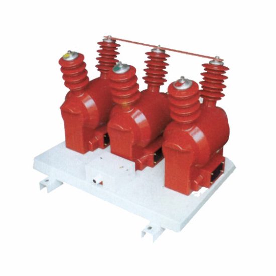
Introduction to the SZW-10R Current Transformer
The SZW-10R is a high-accuracy, indoor-type cast-resin current transformer engineered for reliable operation in 11kV (IEC) / 10kV (domestic) medium-voltage power systems. Designed in strict compliance with IEC 61869-2 and GB/T 20840.2, this instrument transformer serves critical roles in energy metering, protective relaying, and system monitoring. Its construction leverages vacuum pressure impregnation (VPI) epoxy resin technology combined with grain-oriented electrical steel (GOES) cores to ensure long-term stability, minimal phase error, and exceptional dielectric performance.
Operating Principle of Cast-Resin Insulation
Cast-resin insulation in the SZW-10R employs a two-stage VPI process where the primary and secondary windings—along with the GOES magnetic core—are fully encapsulated in cycloaliphatic epoxy resin under vacuum and pressure. This eliminates air voids and moisture ingress pathways, resulting in a homogeneous dielectric structure with a relative permittivity (εr) of approximately 3.8–4.2 and volume resistivity exceeding 1×10¹⁴ Ω·cm at 20°C. Unlike oil-filled alternatives, the solid resin matrix provides intrinsic fire resistance (UL 94 V-0 rated), zero risk of leakage, and immunity to environmental contaminants such as dust or humidity. The thermal class of the insulation system is F (155°C), enabling continuous operation at ambient temperatures up to 40°C with a 10K temperature rise margin under rated load.
Advantages Over Oil-Immersed Designs
Compared to traditional oil-immersed current transformers, the SZW-10R offers significant operational and safety benefits. The absence of flammable insulating oil eliminates fire hazards in confined indoor substations—a critical consideration under IEC 61439-2 for low-voltage switchgear assemblies integrated with MV components. Additionally, the compact mechanical footprint (typically 180 mm height × 120 mm width × 85 mm depth) allows direct mounting within ring-main units (RMUs) or metal-clad switchgear without external tanks or conservators. Maintenance requirements are drastically reduced: no oil sampling, degassing, or level checks are needed over its 25–30 year service life. Dielectric recovery after transient overvoltages is instantaneous due to the non-polar nature of epoxy resin, whereas oil systems may suffer from carbonization or gas bubble formation under similar stress.
Typical Applications Overview
The SZW-10R is predominantly deployed in urban distribution networks, industrial plants, and renewable energy interconnection points where space constraints, safety regulations, and accuracy demands converge. Common use cases include revenue metering at 10kV feeders (accuracy class 0.2S or 0.5S), overcurrent and earth-fault protection (class 5P10 or 10P10), and harmonic monitoring in variable-frequency drive (VFD) environments. Its robust short-time thermal withstand capability (e.g., 20 kA for 1 second) ensures survival during downstream fault events without degradation of metrological performance.
Technical Specifications
The SZW-10R is engineered to deliver precise transformation ratios and stable performance across defined operating envelopes. All parameters align with IEC 61869-2 Clause 5 and GB/T 20840.2 Table 2 requirements.
Rated Electrical Parameters
Key electrical ratings include a highest voltage for equipment (Um) of 12 kV, corresponding to an IEC system voltage of 11 kV and domestic nominal voltage of 10 kV. Standard primary current ratings range from 50 A to 3000 A, with secondary outputs fixed at 1 A or 5 A. Accuracy classes available include 0.2, 0.2S, 0.5, 0.5S for metering, and 5P10, 5P20, 10P10, 10P20 for protection. Rated burden values span 2.5 VA to 30 VA depending on class; for example, a 0.2S class unit typically specifies 5 VA at cos φ = 0.8 lagging. The insulation level meets IEC 60071-1: 28 kV rms power frequency withstand voltage (1 min) and 75 kV peak lightning impulse withstand voltage (1.2/50 μs). Phase displacement is limited to ±10 minutes for 0.2 class and ±30 minutes for 5P10 under rated conditions.
Environmental and Mechanical Ratings
The SZW-10R is rated for indoor installation only, with standard service conditions defined as: ambient temperature range –5°C to +40°C (with derating above 40°C per IEC 60060-1), relative humidity ≤95% non-condensing, and altitude ≤1000 m above sea level. For installations above 1000 m, dielectric strength must be corrected by a factor of 1/(1 + (H – 1000)/7500), where H is altitude in meters. The housing is made of UV-stabilized cycloaliphatic epoxy with tracking resistance ≥600 V (IEC 60112). Mounting is via two M8 threaded inserts on the base flange, compatible with standard DIN rail or bracket systems. Terminal blocks accommodate conductors up to 185 mm² (AWG 3/0) with torque specification of 2.5 N·m.
Core and Winding Construction
The magnetic circuit utilizes CRGO (cold-rolled grain-oriented) silicon steel laminations with a maximum specific loss of 1.0 W/kg at 1.7 T and 50 Hz. Secondary windings are wound with oxygen-free copper (OFC) wire, insulated with Class F enamel (155°C), and embedded directly into the resin matrix to prevent movement-induced microphonics or turn-to-turn shorts. Primary conductors are either solid busbar inserts (for through-type models) or multi-turn windings (for lower current ratios). All internal connections are ultrasonically welded to minimize contact resistance (<10 μΩ). The design ensures a knee-point voltage (Vk) ≥ 100 V for 5P-class units, guaranteeing linear response during fault currents up to 20× rated primary current.
Typical Applications
The SZW-10R’s versatility stems from its dual compliance with international and Chinese standards, making it suitable for diverse grid architectures.
Substation Secondary Metering
In 10kV/0.4kV distribution substations, the SZW-10R enables accurate billing-grade energy measurement when paired with class 0.2S or 0.5S meters. For instance, a 400/5 A ratio unit with 5 VA burden ensures composite error ≤±0.2% at 100% load and ≤±0.35% at 20% load—critical for meeting DL/T 448-2016 technical management regulations in China. The low phase error (<±5 arcmin at 0.2S) minimizes reactive power measurement drift in three-phase systems. Installation within RMUs adjacent to vacuum circuit breakers eliminates external cabling errors and reduces electromagnetic interference from switching transients.
Industrial Power Distribution
Heavy industries such as steel mills or chemical plants deploy the SZW-10R for motor protection and load profiling. A typical 1250/1 A, 10P20 unit feeds differential relays (e.g., SEL-751) to detect internal winding faults in 10kV induction motors. The high saturation point (Vk > 150 V) prevents relay misoperation during motor start-up inrush currents (6–8× FLA). In arc furnace applications, the transformer’s harmonic tolerance (up to 13th order) ensures stable operation despite severe waveform distortion (THD > 25%).
Renewable Energy Integration
Solar PV and wind farms connecting to 10kV grids utilize the SZW-10R for both revenue metering and anti-islanding protection. During cloud-induced irradiance fluctuations, rapid current changes (di/dt > 500 A/ms) are accurately tracked due to the low leakage inductance (<0.5 mH) of the cast-resin design. For grid-code compliance (e.g., NB/T 32004), the CT must maintain accuracy during low-power-factor export (cos φ = 0.95 leading); the SZW-10R achieves this via optimized core permeability and minimized hysteresis loss.
Rural and Suburban Distribution Networks
In remote areas with limited maintenance access, the SZW-10R’s hermetic sealing and corrosion-resistant terminals ensure decades of trouble-free operation. Deployed on pole-mounted transformers or pad-mounted switchgear, these CTs support automated meter reading (AMR) systems and fault location via traveling-wave detection. The wide temperature tolerance (–25°C operational with optional cold-climate variant) accommodates seasonal extremes without recalibration.
Harmonic-Rich Environments
Data centers and EV charging stations generate significant harmonic currents (3rd, 5th, 7th). The SZW-10R’s GOES core exhibits low incremental loss at higher frequencies, maintaining ratio error within ±1% up to 2.5 kHz. This enables accurate harmonic energy billing per IEEE 1459 and prevents nuisance tripping of electronic overload relays.
Compliance with International Standards
The SZW-10R is certified to both global and national regulatory frameworks, ensuring interoperability and legal metrology acceptance.
IEC 61869-2 Compliance Details
Per IEC 61869-2:2012, the SZW-10R undergoes rigorous type testing including temperature rise (Clause 7.3), short-circuit withstand (Clause 7.5), and accuracy verification (Clause 7.7). The standard mandates that protection-class CTs exhibit a limiting primary current (Ip) ≥ rated accuracy limit factor (ALF) × Ipr. For a 5P20 unit, this means the composite error must remain ≤5% at 20× rated primary current. Dielectric tests follow IEC 60060-1: 28 kV rms for 1 minute at power frequency and 75 kV BIL for lightning impulse. Partial discharge levels are limited to ≤10 pC at 1.2 Um/√3 during factory testing.
GB/T 20840.2 Alignment
China’s GB/T 20840.2-2014 mirrors IEC 61869-2 but adds specific requirements for domestic grids. Notably, it mandates a minimum short-time thermal current of 25 kA for 1 second for 10kV CTs (vs. 20 kA in IEC), reflecting higher fault levels in urban Chinese networks. Accuracy verification includes additional test points at 1% and 5% of rated current for S-classes, ensuring precision during light-load nighttime conditions. The standard also requires flame retardancy testing per GB/T 5169.16, which the SZW-10R passes with V-0 rating.
Key Differences Between IEC and Domestic Standards
While IEC 61869-2 permits ALF values up to 40, GB/T 20840.2 caps protection-class ALF at 30 for 10kV systems. Additionally, GB/T specifies mandatory seismic testing (horizontal acceleration 0.3g) for transformers installed in earthquake-prone regions like Sichuan, whereas IEC treats this as optional. Burden definitions also differ slightly: IEC uses apparent power (VA) at cos φ = 0.8, while GB/T allows resistive-only burdens for certain protection applications. Despite these nuances, the SZW-10R is dual-certified, bearing both CE and CQC marks.
On-Site Testing Procedures
Post-installation verification ensures the SZW-10R performs within specified tolerances before energization.
Insulation Resistance Test
Using a 2500 V DC megohmmeter, measure insulation resistance between primary-to-secondary, primary-to-ground, and secondary-to-ground. Acceptance criteria per IEC 60270 require ≥1000 MΩ at 20°C. Correct for temperature using RT = R20 × 2(20–T)/10. Values below 500 MΩ indicate moisture ingress or resin cracking and warrant replacement.
Turns Ratio Test
Apply a low-voltage AC source (5–10 V) to the primary and measure secondary voltage. Calculate actual ratio as Vp/Vs. Tolerance must be within ±0.2% for 0.2 class and ±1% for 5P10. Use a dedicated CT analyzer (e.g., Omicron CT Analyzer) for automated comparison against nameplate data.
Polarity Test
Verify reducing polarity using the DC kick method: connect a 6 V battery momentarily to P1–P2 and observe galvanometer deflection at S1–S2. A positive kick confirms correct polarity (S1 corresponds to P1). Incorrect polarity causes 180° phase shift, leading to relay miscoordination or negative meter readings.
Power Frequency Withstand Voltage Test
Apply 28 kV rms at 50 Hz between primary and grounded secondary/housing for 1 minute. Leakage current must remain <1 mA. This test validates resin integrity after transportation stresses. Perform only if factory test records are unavailable or after major maintenance.
Short-Circuit Test (for CT)
Inject 10× rated secondary current (e.g., 50 A for 5 A secondary) into the secondary winding with primary shorted. Measure voltage drop across secondary terminals; it should not exceed 1.5× rated burden voltage. Excessive drop indicates turn-to-turn shorts or degraded winding insulation.
Preventive Maintenance Guide
Although cast-resin CTs require minimal upkeep, scheduled inspections extend service life and prevent unexpected failures.
Periodic Inspection Protocol
Annual visual checks should confirm: (1) no surface cracks or tracking marks on resin housing, (2) terminal tightness (re-torque to 2.5 N·m if loose), (3) absence of discoloration indicating overheating, and (4) clean, dry surroundings free of conductive dust. Use an infrared camera to detect hot spots (>10K above ambient) at connections during peak load.
Maintenance Intervals and Fault Diagnosis
Every five years, perform insulation resistance and ratio tests as baseline comparisons. Common failure modes include: (a) open secondary circuit during operation—causing core saturation and dangerous overvoltages (>2 kV); (b) moisture-induced partial discharges at resin-air interfaces; and (c) mechanical damage from improper handling. If ratio error exceeds twice the initial value or insulation resistance drops below 200 MΩ, decommission the unit immediately.
Maintenance Schedule Summary
| Interval | Task | Acceptance Criteria |
|---|---|---|
| Annually | Visual inspection, IR thermography | No cracks, ΔT ≤10K |
| 5 Years | Insulation resistance, ratio test | R ≥500 MΩ, ratio error ≤1.5× initial |
| After Fault | Full suite of on-site tests | All parameters within spec |
Conclusion
The SZW-10R 11kV cast-resin current transformer represents a benchmark in reliability, accuracy, and safety for modern medium-voltage infrastructure. By integrating GOES silicon steel cores with VPI epoxy resin encapsulation, it achieves superior thermal stability (Class F insulation), exceptional dielectric strength (28 kV/75 kV BIL), and immunity to environmental degradation. Its dual certification to IEC 61869-2 and GB/T 20840.2 ensures seamless deployment across global and domestic markets—from dense urban substations to remote renewable sites. The transformer’s robust short-circuit withstand (25 kA/1s per GB/T) and precise metrological performance (0.2S class with ±0.2% error) make it indispensable for revenue metering and critical protection schemes. With a design life of 25–30 years and minimal maintenance requirements, the SZW-10R delivers long-term operational economy without compromising on technical rigor. Engineers can confidently specify this unit knowing it meets the most stringent international standards while addressing real-world challenges like harmonic distortion, thermal cycling, and space-constrained installations.
Frequently Asked Questions (FAQ)
Q1: Can the SZW-10R be installed outdoors?
No. The SZW-10R is rated for indoor use only. Outdoor exposure to UV radiation and thermal cycling may degrade the epoxy resin over time. For outdoor applications, consider the SZW-10RW weatherproof variant.
Q2: What is the maximum allowable secondary burden for a 0.5S class SZW-10R?
The maximum burden is 10 VA at cos φ = 0.8 lagging. Exceeding this increases ratio and phase errors beyond class limits. Always verify total loop impedance (wiring + meter + relay) during design.
Q3: Is it safe to leave the secondary open-circuited during maintenance?
Absolutely not. An open secondary during primary current flow induces hazardous voltages (>2 kV) due to core saturation. Always short-circuit secondary terminals with a dedicated shorting link before disconnecting loads.
Q4: How does altitude affect the SZW-10R’s dielectric performance?
Above 1000 m, the power frequency withstand voltage must be derated by 1% per 100 m. At 2000 m, the test voltage becomes 25.2 kV instead of 28 kV. Consult IEC 60071-2 for exact correction factors.
Q5: Can the SZW-10R be used for DC current measurement?
No. Current transformers operate on electromagnetic induction, which requires alternating current. For DC applications, Hall-effect sensors or shunt resistors are required.
Q6: What torque should be applied to the secondary terminals?
Use 2.5 N·m for M6 terminals. Over-torquing can crack the resin housing; under-torquing increases contact resistance and causes localized heating.
Q7: Does the SZW-10R require periodic recalibration?
Not under normal conditions. Cast-resin CTs exhibit excellent long-term stability. Recalibration is only needed if on-site tests indicate performance drift or after exposure to extreme fault currents.