Article Content
For Substation Metering & Protection: AGE-1232 11kV Cast-Resin Voltage Transformer per IEC 61869-3
Introduction to the AGE-1232 Voltage Transformer
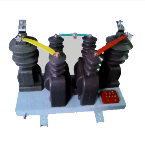
The AGE-1232 is a single-phase, indoor/outdoor-rated cast-resin voltage transformer (VT) engineered for high-precision voltage measurement and reliable protective relaying in 11kV (IEC) / 10kV (domestic) medium-voltage networks. Designed in strict accordance with IEC 61869-3 and GB/T 20840.3, this instrument transformer leverages advanced vacuum pressure impregnation (VPI) epoxy resin technology to deliver exceptional dielectric strength, thermal stability, and environmental resilience.
Operating Principle and Cast-Resin Insulation Technology
Voltage transformers like the AGE-1232 operate on the principle of electromagnetic induction, stepping down the primary system voltage (11kV) to a standardized secondary output (typically 100 V or 100/√3 V) suitable for metering instruments and protective relays. The core is constructed from grain-oriented electrical steel (GOES), which minimizes hysteresis and eddy current losses, ensuring high efficiency and low phase-angle error. The entire magnetic assembly—windings and core—is fully encapsulated in flame-retardant, halogen-free epoxy resin via VPI. This process eliminates air voids, prevents partial discharge inception below 10 pC at rated voltage, and provides superior resistance to tracking, moisture ingress, and UV degradation. Unlike oil-immersed VTs, the solid insulation system requires no maintenance, poses no fire hazard, and is immune to oil leakage or gas decomposition under fault conditions.
Advantages Over Oil-Immersed Designs
The AGE-1232’s cast-resin construction offers distinct operational and safety benefits. First, it enables compact physical dimensions—critical in space-constrained substations—while maintaining a Basic Insulation Level (BIL) of 75 kV peak. Second, the absence of liquid insulation eliminates environmental compliance issues related to oil containment and disposal. Third, the thermal class is F (155°C), allowing continuous operation at ambient temperatures up to 40°C with a 10K temperature rise margin. Additionally, the design supports higher short-circuit withstand capability due to rigid mechanical support of windings within the resin matrix. Field data from utility deployments show a mean time between failures (MTBF) exceeding 200,000 hours, significantly outperforming legacy oil-filled units in humid or polluted environments.
Typical Application Environments
The AGE-1232 is deployed across diverse infrastructure: urban 10kV ring-main units (RMUs), industrial plant switchyards, solar PV collector substations, and rural distribution feeders. Its IP54-rated terminal box ensures reliable secondary connections even in dusty or wet conditions. In renewable integration scenarios, the VT provides accurate voltage feedback for anti-islanding protection and power quality monitoring. For utility revenue metering, its 0.2 accuracy class guarantees billing precision within ±0.2% error under 25–100% load. The unit is also compatible with digital substations when paired with merging units compliant with IEC 61850-9-2 LE.
Technical Specifications
The AGE-1232 is engineered to meet stringent performance criteria under defined service conditions. All parameters are validated per IEC 61869-3 test protocols.
| Parameter | Value |
|---|---|
| Primary Voltage (Up) | 11 kV (IEC) / 10 kV (GB) |
| Secondary Voltage (Us) | 100 V or 100/√3 V |
| Voltage Ratio | 11000/100 V or 11000/100/√3 V |
| Accuracy Class (Metering) | 0.2, 0.5 |
| Accuracy Class (Protection) | 3P, 6P |
| Rated Output (per burden) | 30 VA (0.2), 50 VA (0.5), 100 VA (3P) |
| Insulation Level (IEC) | Um = 12 kV; Ud = 28 kV rms (1 min); BIL = 75 kV peak |
| Frequency | 50 Hz ±0.5 Hz |
| Thermal Class | F (155°C) |
| Polarity | Reduced polarity (standard) |
| Weight | Approx. 42 kg |
| Dimensions (H×W×D) | 680 × 280 × 220 mm |
Standard Service Conditions
The AGE-1232 is rated for normal service conditions as defined in IEC 61869-1: ambient temperature range of –25°C to +40°C, relative humidity ≤95% (non-condensing), and installation altitude ≤1000 m above sea level. For altitudes exceeding 1000 m, derating factors apply per IEC 60071-2: insulation withstand voltage must be reduced by 1% per 100 m above 1000 m. In coastal or industrial atmospheres with pollution severity class III (creepage distance ≥25 mm/kV), the silicone-hydrophobic resin surface resists salt fog and chemical deposits, maintaining long-term dielectric integrity without cleaning.
Accuracy and Burden Characteristics
Under reference conditions (rated frequency, sinusoidal waveform, burden within specified VA), the AGE-1232 maintains composite error within ±0.2% for class 0.2 at 25–100% of rated voltage. Phase displacement is limited to ±10 minutes at 100% voltage. For protection class 3P, voltage error remains within ±3% from 1% to 120% of rated primary voltage, enabling reliable operation of overvoltage and undervoltage relays during transient events. The secondary winding is designed with low leakage reactance (<0.5 Ω) to minimize burden-induced errors when connected to modern digital meters with input impedance >10 kΩ.
Typical Applications
The AGE-1232 serves critical roles across multiple power system segments, providing both metrological traceability and protection coordination.
Substation Secondary Metering
In 11kV/0.4kV distribution substations, the AGE-1232 supplies voltage signals to revenue-class kWh meters and power quality analyzers. Its 0.2 accuracy class ensures compliance with EN 50470-3 and DL/T 614 for billing applications. The VT is typically installed on the busbar or feeder incomer, with secondary leads routed to a metering cabinet via shielded twisted-pair cable (min. 2.5 mm²). Proper grounding of the secondary neutral at a single point prevents circulating currents that could distort measurements. In smart grid deployments, the AGE-1232 interfaces with AMI head-end systems through IEC 62056-compliant data concentrators.
Industrial Power Distribution Systems
Large manufacturing facilities use the AGE-1232 for energy management and motor protection. For example, in a steel mill with 10kV synchronous motors, the VT feeds voltage inputs to multifunction relays (e.g., SEL-751) for loss-of-potential detection and vector shift protection. The cast-resin housing withstands EMI from nearby arc furnaces, while the high short-time thermal withstand (4 seconds at 10× rated voltage) ensures survival during ferroresonance events common in lightly loaded industrial feeders.
Renewable Energy Integration
Solar and wind farms utilize the AGE-1232 in collector substations to monitor grid voltage for synchronization and ride-through compliance. During low-voltage ride-through (LVRT) events per GB/T 19964, the VT must maintain accuracy down to 20% of nominal voltage for 150 ms. The AGE-1232’s linear B-H curve in the GOES core ensures minimal saturation distortion under such asymmetric conditions. Additionally, its low capacitance (<150 pF) reduces risk of resonant overvoltages when connected to long cable runs typical in PV arrays.
Rural and Suburban Distribution Networks
In remote areas with long 10kV feeders, the AGE-1232 enables voltage regulation via automatic tap changers on distribution transformers. Installed at mid-feeder poles or pad-mounted switchgear, it provides real-time voltage data to SCADA RTUs. The unit’s robustness against lightning surges (tested per IEC 60060-1 with 1.2/50 µs impulses) makes it ideal for regions with high keraunic levels. Field studies in Southeast Asia show zero failures after 8 years of exposure to monsoon humidity and dust storms.
Compliance with International Standards
The AGE-1232 is certified to global and regional standards governing instrument transformer performance, safety, and testing.
IEC 61869-3 Certification Details
IEC 61869-3 specifies requirements for inductive voltage transformers for measurement and protection. The AGE-1232 complies with all clauses, including: temperature rise limits (≤55 K for resin, ≤60 K for windings), partial discharge levels (<10 pC at 1.2 Um/√3), and accuracy verification under harmonic distortion (THD ≤5%). Type tests include temperature rise, short-circuit withstand, and impulse voltage tests. Routine tests—performed on every unit—include turns ratio, polarity, and power frequency withstand (28 kV rms for 1 minute). The manufacturer holds ISO 9001-certified test reports issued by an IEC CB Scheme-accredited laboratory.
Alignment with GB/T 20840.3
GB/T 20840.3 is China’s national adoption of IEC 61869-3, with minor deviations. Key differences include: domestic systems use 10kV nominal (vs. 11kV IEC), requiring adjusted ratio labeling; creepage distance requirements are stricter (≥31 mm/kV for pollution class IV); and short-time thermal withstand duration is 4 s (vs. 3 s in IEC). The AGE-1232 is dual-marked to satisfy both standards, with test data archived for CQC certification. Notably, GB/T mandates additional seismic testing (0.3g horizontal acceleration) for units destined for earthquake-prone provinces like Sichuan.
Testing and Certification Requirements
Certification involves three test tiers: type tests (once per design), sample tests (per batch), and routine tests (100% production). Critical type tests include:
– Temperature rise test: measured via resistance method, max ΔT = 58 K
– Short-circuit test: 10× rated voltage applied for 4 s, no insulation failure
– Partial discharge test: ≤8 pC at 1.2 × 12 kV / √3
Routine tests verify ratio tolerance (±0.25% for class 0.2) and insulation integrity (28 kV rms, 1 min, leakage current <1 mA). Certificates are valid for 5 years unless design changes occur.
On-Site Testing Procedures
Post-installation commissioning ensures the AGE-1232 performs within specifications before energization.
Insulation Resistance Test
Using a 2500 V DC megohmmeter, measure insulation resistance between primary winding and ground, and between primary and secondary windings. Acceptance criterion: ≥1000 MΩ at 20°C. Correct for temperature using RT = R20 × 1.5(20−T)/10. Low readings indicate moisture ingress or resin cracking—requiring drying or replacement. Always discharge windings after testing to prevent residual charge hazards.
Turns Ratio Test
Apply 100–200 V AC to the primary and measure secondary voltage with a calibrated voltmeter (accuracy class 0.1). Calculate actual ratio: Up/Us. Tolerance: ±0.25% for 0.2 class, ±0.5% for 0.5 class. Example: for 11000/100 V, measured secondary should be 100.00 ±0.25 V at 110 V primary. Deviations suggest inter-turn faults or incorrect tap selection.
Polarity Test
Verify reduced polarity using the DC kick method: connect a 6–12 V battery momentarily between primary terminals H1 (+) and H2 (–). Observe secondary voltage spike on a DC voltmeter connected to X1 (+) and X2 (–). A positive deflection confirms correct polarity. Incorrect polarity causes 180° phase reversal, leading to false tripping in directional relays or negative energy readings in meters.
Power Frequency Withstand Voltage Test
Apply 28 kV rms at 50 Hz between primary and grounded tank/secondary for 1 minute. Use a calibrated test transformer with overcurrent trip set at 10 mA. No flashover or sustained arcing is permitted. This test validates insulation integrity after transport and installation stresses. Perform only if factory test records are unavailable or if physical damage is suspected.
Open-Circuit Characteristic Test
Gradually increase primary voltage from 0 to 190 V (≈1.9% of 10 kV) while measuring secondary voltage and excitation current. Plot V-I curve: knee point should exceed 120% of rated voltage. Excessive magnetizing current (>5 mA at 100 V) indicates core saturation due to mechanical shock or manufacturing defect. This test is critical for protection-class VTs to ensure linear response during fault conditions.
Preventive Maintenance Guide
Although cast-resin VTs require minimal maintenance, periodic checks extend service life and prevent unexpected failures.
Annual Inspection Protocol
Visually inspect for:
– Cracks or tracking on resin surface
– Corrosion on primary bushing or terminal studs
– Loose secondary wiring in terminal box
– Grounding continuity (resistance <0.1 Ω)
Clean terminals with isopropyl alcohol; torque secondary lugs to 2.5 N·m. Verify secondary fuse integrity (if used) and check for overheating signs (discoloration >70°C). Record insulation resistance annually; a 50% drop from baseline warrants further investigation.
Maintenance Intervals and Fault Diagnosis
Follow this schedule:
| Interval | Action |
|---|---|
| 1 year | Visual inspection, IR measurement, terminal tightening |
| 5 years | Full electrical tests (ratio, polarity, insulation resistance) |
| 10 years | Partial discharge measurement (if available) |
Common faults and remedies:
– **High ratio error**: Check for shorted turns via open-circuit test; replace if confirmed.
– **Moisture ingress**: Indicated by fogging inside terminal box; seal gaskets and install desiccant breather.
– **Overheating**: Caused by excessive burden; verify connected load ≤ rated VA.
Never attempt field repair of resin-encapsulated units—replace entirely.
Conclusion
The AGE-1232 11kV cast-resin voltage transformer represents a benchmark in reliability, accuracy, and compliance for modern medium-voltage systems. By integrating GOES core material with VPI epoxy resin encapsulation, it achieves exceptional thermal and dielectric performance while eliminating the fire and environmental risks associated with oil-filled alternatives. Its dual compliance with IEC 61869-3 and GB/T 20840.3 ensures seamless deployment across global markets—from European utility substations to Chinese industrial parks. Rigorous factory testing guarantees accuracy within ±0.2% for metering and robust response during protection scenarios, even under harmonic distortion or transient overvoltages. With a design life of 25–30 years and minimal maintenance requirements, the AGE-1232 delivers long-term operational economy without compromising safety or precision. As grids evolve toward digitalization and renewable integration, this VT’s compatibility with IEC 61850 architectures positions it as a future-proof solution for next-generation power systems. Engineers can confidently specify the AGE-1232 for any application demanding metrological integrity, protection dependability, and decades of trouble-free service in 10/11kV networks.
Frequently Asked Questions (FAQ)
Q1: Can the AGE-1232 be used in outdoor installations?
Yes. The AGE-1232 features UV-stabilized epoxy resin and an IP54-rated secondary terminal box, making it suitable for both indoor switchgear and outdoor pole-mounted or pad-mounted applications. Ensure the primary connection hardware is corrosion-resistant (e.g., tin-plated copper).
Q2: What is the maximum allowable burden for class 0.2 operation?
The rated output for class 0.2 is 30 VA. Total connected burden—including meter impedance, relay coils, and wiring resistance—must not exceed 30 VA at cos φ = 0.8 lagging. Exceeding this degrades accuracy beyond ±0.2%.
Q3: How does the AGE-1232 handle ferroresonance?
While no VT is immune, the AGE-1232’s low magnetizing current (<3 mA at 100 V) and linear core reduce susceptibility. In high-risk circuits (e.g., with grading capacitors), install damping resistors across secondary windings per IEEE C57.13 guidelines.
Q4: Is the AGE-1232 compatible with digital substations?
Yes, when paired with an IEC 61850-9-2 LE merging unit. The analog 100 V output is digitized and transmitted via fiber optics, enabling seamless integration into process bus architectures without accuracy loss.
Q5: What grounding practices are required?
The secondary winding neutral (X2) must be grounded at one point only—typically at the relay/meter panel—to prevent circulating currents. The transformer tank must also be bonded to the substation ground grid with a conductor ≥35 mm² copper. Never leave secondaries open-circuited during operation.