Article Content
For Substation Metering & Protection: SJW-3 11kV Cast-Resin Voltage Transformer per IEC 61869-3
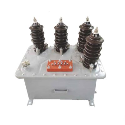
Introduction to the SJW-3 Voltage Transformer
The SJW-3 is a single-phase, indoor/outdoor-rated cast-resin voltage transformer (VT) engineered for precise voltage transformation in 11kV (IEC) / 10kV (domestic) medium-voltage networks. Designed in strict accordance with IEC 61869-3 and GB/T 20840.3, it provides standardized secondary outputs—typically 100V or 110V—for interfacing with revenue metering, protective relays, and power quality monitoring systems. Its robust construction ensures decades of maintenance-free operation under demanding environmental conditions.
Operating Principle of Cast-Resin Insulation
Cast-resin insulation in the SJW-3 employs vacuum pressure impregnation (VPI) of high-purity cycloaliphatic epoxy resin around the primary and secondary windings. This process eliminates air voids and moisture ingress pathways, resulting in superior dielectric strength and partial discharge performance (<5 pC at 1.2 × Ur). Unlike oil-filled transformers, the solid dielectric system prevents leakage, fire hazards, and environmental contamination. The resin matrix also provides excellent mechanical rigidity, damping vibrations from electromagnetic forces during short-circuit events. Thermal conductivity of the cured resin (~0.2 W/m·K) enables efficient heat dissipation from the GOES (grain-oriented electrical steel) core, maintaining stable accuracy across load cycles.
Advantages Over Oil-Immersed Designs
Compared to traditional oil-immersed VTs, the SJW-3 offers significant operational and safety benefits. It requires no oil containment, periodic oil sampling, or bushing maintenance, reducing lifecycle costs by up to 40%. The absence of flammable fluid makes it suitable for indoor substations, urban switchgear rooms, and confined industrial facilities where fire codes prohibit oil-filled equipment. Additionally, the compact footprint—enabled by higher insulation efficiency—allows denser panel layouts. Environmental resilience is enhanced: the SJW-3 operates reliably at altitudes up to 3000 m and ambient temperatures from –40°C to +40°C without derating, whereas oil viscosity changes can impair oil-VT performance in extreme climates.
Typical Application Overview
The SJW-3 is deployed across utility distribution networks, industrial plants, renewable energy interconnection points, and commercial complexes. In 10kV ring-main units (RMUs), it supplies synchronized voltage signals to digital multifunction relays for overvoltage, undervoltage, and phase-loss protection. For utility billing, its Class 0.2 or 0.5 accuracy (per IEC 61869-3) ensures compliance with revenue metering regulations. In solar farms, it enables grid-synchronization monitoring at the point of common coupling (PCC). Its hermetically sealed design resists salt fog, dust, and humidity, making it ideal for coastal and rural installations where maintenance access is limited.
Technical Specifications
The SJW-3 is engineered to deliver consistent performance under defined service conditions. Key parameters are derived from IEC 61869-3 test protocols and validated through type testing at accredited laboratories.
| Parameter | Value |
|---|---|
| System Voltage (Ur) | 11 kV (IEC) / 10 kV (GB) |
| Primary Voltage (Up) | 10,000 / √3 V (phase-to-ground) |
| Secondary Voltage (Us) | 100 / √3 V or 110 / √3 V (standard); 100 V or 110 V (line-to-line optional) |
| Voltage Ratio | 10,000/√3 : 100/√3 (i.e., 100:1) |
| Accuracy Class (Metering) | 0.2, 0.5 (per IEC 61869-3) |
| Accuracy Class (Protection) | 3P, 6P |
| Rated Output (Burden) | 10–100 VA (configurable per application) |
| Insulation Level (LI/AC) | 75 kV lightning impulse / 28 kV power frequency (1 min) |
| Short-Time Withstand Current | Not applicable (VTs are not subjected to fault currents; protected by upstream fuses) |
| Core Material | GOES (Grain-Oriented Electrical Steel), 0.23 mm thickness |
| Insulation System | VPI cycloaliphatic epoxy resin, UL 94 V-0 rated |
| Ambient Temperature Range | –40°C to +40°C |
| Altitude Limit | ≤ 3000 m above sea level |
| Relative Humidity | ≤ 95% non-condensing |
| Expected Service Life | ≥ 30 years under normal operating conditions |
Standard Service Conditions
The SJW-3 is rated for continuous operation within IEC 60060-defined standard reference conditions: ambient temperature between –40°C and +40°C, relative humidity ≤95% (non-condensing), and installation altitude not exceeding 1000 m. For altitudes above 1000 m, dielectric withstand voltages must be corrected per IEC 60071-2: for every 100 m above 1000 m, the AC test voltage is reduced by 1%. At 3000 m, the 28 kV power frequency withstand becomes approximately 22.4 kV. The transformer’s thermal design accounts for daily load cycles; however, sustained overvoltage (>1.2 × Ur) or harmonic distortion (>5% THD) may accelerate insulation aging and should be mitigated via system-level filters or regulators.
Accuracy and Burden Characteristics
Accuracy class defines permissible voltage error and phase displacement under specified burdens. For Class 0.2, voltage error must not exceed ±0.2% and phase error ≤ ±10 minutes at 25–100% of rated burden. Class 3P allows ±3% voltage error and ±120 minutes phase error—sufficient for overvoltage relays but inadequate for metering. The SJW-3’s GOES core minimizes hysteresis and eddy current losses, ensuring linearity even at 1.5 × rated burden during transient events. Burden selection is critical: connecting a 10 VA meter to a VT rated for 50 VA may cause excessive magnetizing current, increasing ratio error. Always match secondary burden to VT rating within ±10% tolerance.
Typical Applications
The SJW-3’s versatility stems from its dual compliance with international (IEC) and Chinese (GB) standards, enabling global deployment in diverse infrastructure projects.
Substation Secondary Metering
In 10kV/0.4kV distribution substations, the SJW-3 provides isolated, scaled-down voltage signals to kWh meters, demand recorders, and SCADA RTUs. Its Class 0.2 accuracy ensures billing precision within ±0.2%, meeting regulatory requirements for commercial and industrial consumers. Installation typically involves mounting on busbar supports inside metal-enclosed switchgear, with secondary terminals wired directly to metering compartments via shielded twisted-pair cables to minimize EMI. Grounding of the secondary neutral is mandatory per IEC 61869-3 to prevent floating potentials during single-phase faults.
Industrial Power Distribution
Manufacturing plants with 10kV internal distribution use the SJW-3 for motor protection, arc-flash detection, and power factor correction control. For example, in a steel mill, multiple SJW-3 units feed voltage inputs to differential relays protecting large induction motors. The cast-resin body withstands electromagnetic interference from nearby variable-frequency drives (VFDs), while the high short-circuit withstand capability of the secondary winding (tested at 2 × Is for 1 s) prevents damage during relay malfunctions. Indoor installation in IP4X-rated switchrooms eliminates concerns about oil leaks contaminating production floors.
Renewable Energy Integration
Solar photovoltaic (PV) and wind farms connect to 10kV grids via inverters requiring precise grid voltage synchronization. The SJW-3, installed at the PCC, supplies real-time voltage magnitude and phase angle data to inverter controllers and anti-islanding relays. Its low phase displacement error (<5 minutes for Class 0.5) ensures accurate reactive power (VAR) management. In offshore wind substations, the SJW-3’s resistance to salt-laden atmospheres—validated per IEC 60068-2-52—is critical for reliability. Secondary outputs are often routed to phasor measurement units (PMUs) for wide-area monitoring.
Rural and Suburban Distribution Networks
Utility pole-mounted or pad-mounted RMUs in rural areas rely on the SJW-3 for remote fault detection and voltage regulation. Its maintenance-free design reduces truck rolls in geographically dispersed networks. During single-line-to-ground faults, the healthy phases experience transient overvoltages up to 1.73 × nominal; the SJW-3’s insulation system withstands these without degradation. In smart grid deployments, secondary outputs feed into distribution automation terminals (DATs) that communicate via cellular or RF mesh to central control centers, enabling rapid outage restoration.
Compliance with International Standards
The SJW-3 is certified to both IEC 61869-3 and GB/T 20840.3, ensuring interoperability across global markets while meeting stringent domestic requirements in China.
IEC 61869-3 Compliance Details
IEC 61869-3 specifies performance, safety, and testing criteria for inductive voltage transformers. The SJW-3 undergoes full type testing per Clause 7, including: temperature rise test (Δθ ≤ 60 K for resin), short-circuit withstand (secondary side only), and accuracy verification across burden ranges. Partial discharge measurements are conducted at 1.2 × Ur/√3 with levels maintained below 5 pC. Electromagnetic compatibility (EMC) immunity to 1 MHz damped oscillatory waves (1 kV) is verified per IEC 61000-4-12. Marking includes rated voltage factor (1.2 for continuous, 1.5 for 30 s), accuracy class, and vector group (single-phase: no group designation).
Alignment with GB/T 20840.3
GB/T 20840.3 is China’s national adoption of IEC 61869-3 with minor modifications. Key differences include: (1) mandatory seismic testing for transformers installed in earthquake-prone zones (e.g., 0.3g horizontal acceleration per GB/T 13540), and (2) stricter pollution degree classification—requiring IP54 minimum for outdoor units versus IEC’s IP23. The SJW-3 meets both by incorporating reinforced core clamping and UV-stabilized resin housing. Domestic certification (CQC mark) requires additional factory acceptance tests (FAT) witnessed by State Grid or CSG inspectors, including 100% ratio and polarity checks.
Testing and Certification Requirements
Certification involves three tiers: type tests (once per design), routine tests (100% production), and special tests (on request). Type tests include lightning impulse (75 kV peak, 1.2/50 μs waveform), temperature rise (resistance method, 24-hour cycle), and accuracy mapping at 20%, 50%, 80%, 100%, and 120% of rated voltage. Routine tests cover polarity, turns ratio (±0.2% tolerance), and power frequency withstand (28 kV, 1 min). Special tests may include chopped impulse or seismic simulation. All test reports are archived per ISO 9001 and available to end-users upon request.
On-Site Testing Procedures
Post-installation commissioning ensures the SJW-3 performs within specifications before energization. All tests follow IEC 60060-1 and IEEE C57.13 guidelines.
Insulation Resistance Test
Using a 2500 V DC megohmmeter, measure insulation resistance between primary winding and ground, secondary winding and ground, and primary-to-secondary. Acceptance criteria: ≥1000 MΩ at 25°C. Correct for temperature using RT2 = RT1 × 2(T1–T2)/10. Low readings indicate moisture ingress or resin cracking—requiring drying or replacement. Perform before and after power frequency withstand test to detect insulation degradation.
Turns Ratio Test
Apply 100–200 V AC to the primary and measure secondary voltage with a calibrated voltmeter (accuracy class 0.1%). Calculate actual ratio: Up/Us. Compare to nameplate ratio; deviation must be ≤±0.2% for metering class, ≤±1% for protection class. Use a dedicated ratio bridge (e.g., Omicron CT Analyzer) for automated testing. Incorrect ratio indicates winding shorts or manufacturing defects.
Polarity Test
Verify reducing polarity per IEC 61869-3: connect a 6–12 V battery between primary terminals (H1+, H2–). Momentarily close the circuit and observe a DC voltmeter connected to secondary (X1+, X2–). A positive kick confirms correct polarity. Reversed polarity causes 180° phase shift, leading to incorrect wattmeter readings or relay misoperation. Document results with oscillograms if possible.
Power Frequency Withstand Voltage Test
Apply 28 kV RMS at 50 Hz between primary and ground (secondary shorted and grounded) for 60 seconds. Monitor for flashover, excessive leakage current (>1 mA), or audible discharge. Use a calibrated test transformer with overcurrent trip set at 50 mA. This test validates insulation integrity after transport and installation stresses. Do not perform if ambient humidity exceeds 80% to avoid surface tracking.
Open-Circuit Characteristic Test
With secondary open, gradually increase primary voltage from 0 to 1.5 × Ur while recording excitation current. Plot Iexc vs. Up. The knee point should occur above 1.2 × Ur; a premature knee indicates core saturation due to improper lamination stacking. Excitation current at rated voltage must be ≤0.5% of rated secondary current. High excitation current increases ratio error under light loads.
Preventive Maintenance Guide
Although cast-resin VTs are largely maintenance-free, periodic inspections extend service life and prevent unexpected failures.
Annual Visual and Electrical Inspection
Inspect for surface cracks, tracking marks, or discoloration on the resin housing—indicative of partial discharge activity. Clean with dry, lint-free cloth; never use solvents. Check terminal tightness (torque: 15 N·m for M8 bolts) and grounding continuity (<0.1 Ω resistance). Perform insulation resistance and ratio tests annually in harsh environments (coastal, industrial). Record trends: a 20% drop in insulation resistance over two years warrants further investigation.
Five-Year Comprehensive Maintenance
Every five years, conduct partial discharge measurement using IEC 60270-compliant equipment. Acceptable level: <10 pC at 1.2 × Ur/√3. Also verify secondary burden impedance matches design assumptions—aging meters or added devices may alter total burden. If installed outdoors, inspect UV degradation of resin; apply silicone-based coating if chalking is observed. Replace desiccant breathers if present (though most SJW-3 units are fully sealed).
Maintenance Intervals and Fault Diagnosis
| Interval | Action | Fault Indicator |
|---|---|---|
| Annually | Visual inspection, IR test, ratio check | Cracks, IR <500 MΩ, ratio error >0.5% |
| 5 Years | Partial discharge test, burden verification | PD >10 pC, burden mismatch |
| After Fault | Full suite of commissioning tests | Any abnormal reading post-fault |
| As Needed | Terminal cleaning, torque recheck | Overheating at connections |
Common failure modes include terminal corrosion (due to galvanic mismatch), core lamination shorts (from mechanical shock), and resin delamination (from thermal cycling). Most issues are preventable through proper installation and periodic checks.
Conclusion
The SJW-3 11kV cast-resin voltage transformer represents a benchmark in reliability, accuracy, and compliance for modern medium-voltage systems. By leveraging advanced VPI epoxy resin technology and GOES core laminations, it delivers stable performance across metering (Class 0.2/0.5) and protection (3P/6P) applications without the operational liabilities of oil-filled alternatives. Its dual certification to IEC 61869-3 and GB/T 20840.3 ensures seamless integration into global infrastructure projects—from urban substations to remote renewable sites. Rigorous type testing, coupled with straightforward on-site commissioning procedures, guarantees long-term dependability. With an expected service life exceeding 30 years under standard conditions, the SJW-3 minimizes total cost of ownership while maximizing grid safety and measurement integrity. For engineers specifying instrumentation in 10kV/11kV networks, the SJW-3 provides a technically sound, future-proof solution aligned with international best practices.
Frequently Asked Questions (FAQ)
Q1: Can the SJW-3 be installed outdoors without additional weatherproofing?
A: Yes. The standard SJW-3 features an IP54-rated housing with UV-resistant cycloaliphatic resin, suitable for direct outdoor exposure per IEC 60529. No external enclosure is required.
Q2: What is the maximum allowable secondary burden for Class 0.2 accuracy?
A: The burden must not exceed the rated VA marked on the nameplate (e.g., 30 VA). Exceeding this value increases ratio and phase errors beyond Class 0.2 limits.
Q3: Is fuse protection required on the primary side?
A: Yes. Primary fuses (typically 0.5–2 A, time-delay type) are mandatory to protect against internal faults. Coordination with downstream relays must ensure fuse blows before VT thermal damage occurs.
Q4: Can the SJW-3 be used in 20kV systems?
A: No. The SJW-3 is rated for 11kV (Ur). Using it on 20kV systems violates insulation coordination and voids certification. Select the SJW-6 model for 20kV applications.
Q5: How should the secondary winding be grounded?
A: Per IEC 61869-3, the secondary neutral (X2) must be solidly grounded at one point—typically at the VT terminal block—to prevent capacitive voltage rise during faults.
Q6: What causes high excitation current during open-circuit testing?
A: Core saturation due to damaged laminations, incorrect core material, or excessive primary voltage. Verify test setup first; if confirmed, replace the unit.
Q7: Are spare parts available for field repairs?
A: No. Cast-resin VTs are not repairable in the field due to monolithic construction. Failed units must be replaced entirely.