Article Content
For Substation Metering & Protection: SZW-6 11kV Cast-Resin Voltage Transformer per IEC 61869-3
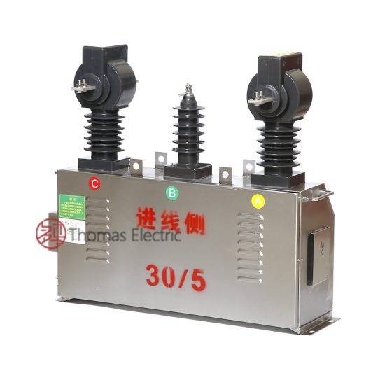
Introduction to the SZW-6 Voltage Transformer
The SZW-6 is a single-phase, electromagnetic cast-resin voltage transformer (VT) engineered for precise voltage transformation in 11kV (IEC nominal) or 10kV (domestic system) medium-voltage networks. Designed in strict accordance with IEC 61869-3 and GB/T 20840.3, it delivers reliable galvanic isolation between primary high-voltage circuits and secondary instrumentation or protective relaying systems. Its core function is to step down system voltage to standardized secondary levels—typically 100 V or 100/√3 V—for safe interfacing with meters, synchro-check relays, fault locators, and revenue-grade metering equipment.
Operating Principle of Cast-Resin Insulation
The SZW-6 employs vacuum pressure impregnation (VPI) epoxy resin technology to encapsulate its magnetic core and windings. This process involves placing pre-wound coils and grain-oriented electrical steel (GOES) cores into a mold, evacuating air under vacuum, and then injecting thermosetting epoxy resin under pressure. The result is a monolithic, void-free insulation structure with superior dielectric strength (≥30 kV/mm), excellent tracking resistance (CTI ≥600), and minimal partial discharge (<5 pC at 1.2 × Ur). Unlike oil-filled alternatives, the solid resin matrix eliminates fire hazards, environmental leakage risks, and maintenance-intensive oil sampling. The resin’s coefficient of thermal expansion closely matches that of copper and steel, minimizing mechanical stress during thermal cycling from –40°C to +70°C ambient conditions.
Advantages Over Oil-Immersed Designs
Compared to traditional oil-immersed VTs, the SZW-6 offers significant operational and safety benefits. Its dry-type construction eliminates flammability concerns, making it suitable for indoor substations, urban switchgear rooms, and confined industrial facilities where fire codes prohibit oil-filled equipment. The absence of oil also removes the need for conservator tanks, Buchholz relays, and periodic oil testing—reducing lifecycle costs by up to 30%. Furthermore, the compact footprint (typical height: 650 mm, base diameter: 280 mm) enables direct mounting on 11kV busbars without external supports. Electromagnetic performance is enhanced through low-loss GOES cores (losses ≤0.8 W/kg at 1.7 T, 50 Hz), ensuring accuracy class stability even under harmonic distortion (THD ≤5%). The resin’s hydrophobic surface resists moisture absorption (<0.1% weight gain after 24h immersion), critical for coastal or high-humidity environments.
Typical Applications Overview
The SZW-6 is deployed across diverse power infrastructure segments requiring accurate voltage sensing. Primary use cases include utility-owned 11kV/10kV distribution substations for kWh metering and overvoltage protection, industrial plants with motor control centers needing undervoltage lockout, and renewable integration points (e.g., solar farms) where grid synchronization relies on precise phase-angle measurement. Its robust design supports both indoor switchgear (IP2X) and outdoor pole-mounted installations (with optional silicone rubber sheds for pollution class III/IV). Secondary outputs are typically configured as 0.2/3P or 0.5/3P accuracy classes—enabling dual-purpose use: Class 0.2 for revenue metering per IEC 62053-22, and Class 3P for protection functions like earth-fault detection in unearthed or resonant-grounded systems.
Technical Specifications
The SZW-6 is engineered to meet stringent performance criteria under defined service conditions. All parameters align with IEC 61869-3:2011 and GB/T 20840.3-2013, ensuring interoperability in global and domestic grids.
| Parameter | Value |
|---|---|
| Primary Rated Voltage (Ur) | 11 kV (IEC) / 10 kV (GB) |
| Secondary Rated Voltage | 100 V or 100/√3 V |
| Voltage Ratio | 11000/100 V, 11000/100/√3 V, 10000/100 V, etc. |
| Accuracy Classes | Metering: 0.2, 0.5; Protection: 3P, 6P |
| Rated Output (per burden) | 10–100 VA (e.g., 30 VA @ 0.2 class) |
| Insulation Level (Um/Up1/Up2) | 12 kV / 75 kV (1 min) / 95 kV (LI) |
| Short-Time Thermal Withstand | 1 s @ 16 kA (symmetrical) |
| Frequency | 50 Hz or 60 Hz |
| Core Material | Grain-Oriented Electrical Steel (GOES), M4 grade |
| Insulation System | VPI Epoxy Resin, UL 1446 Class F (155°C) |
Standard Service Conditions
The SZW-6 operates reliably under IEC 60060-defined standard reference conditions: ambient temperature range of –40°C to +40°C (with derating above +40°C), relative humidity ≤95% non-condensing, and installation altitude ≤1000 m above sea level. For altitudes exceeding 1000 m, insulation withstand voltages must be corrected per IEC 60071-2 (e.g., +1% per 100 m above 1000 m for LI tests). The transformer is designed for continuous operation at rated voltage and frequency, with permissible overvoltage of 1.2 × Ur for 30 seconds and 1.5 × Ur for 1 second during transient events. Pollution degree is classified as II (non-conductive dust) for indoor use or III (conductive pollution) for outdoor applications when equipped with creepage-extending sheds (minimum creepage distance: 25 mm/kV).
Electrical Performance Characteristics
Voltage error and phase displacement are tightly controlled per accuracy class. At 0.2 class, voltage error must not exceed ±0.2% and phase error ≤±10 minutes at 25–100% of rated burden. For protection class 3P, composite error ≤3% at 5%–100% of rated voltage and specified burden. Burden is defined as the total impedance (resistive + reactive) connected to the secondary terminals, typically expressed in VA at cos φ = 0.8 lagging. The SZW-6 maintains accuracy even with unbalanced burdens across multiple secondary windings (e.g., metering + protection outputs). Core excitation current is minimized (<0.5% of rated primary current at 1.9 × Ur) to prevent ferroresonance in isolated-neutral systems—a common failure mode in VTs.
Typical Applications
The SZW-6’s versatility stems from its dual compliance with international and Chinese standards, enabling deployment across utility, industrial, and renewable sectors.
Substation Secondary Metering
In 11kV/10kV distribution substations, the SZW-6 provides the voltage input for three-phase kWh meters used in billing and load profiling. Configured with 0.2-class secondary windings, it ensures compliance with regulatory accuracy requirements (e.g., China’s DL/T 448-2016). The transformer is typically installed on the incoming feeder or bus coupler, with secondary cables routed to a metering cabinet via shielded twisted pairs to minimize EMI. In ring-main units (RMUs), its compact size allows integration alongside SF6 or vacuum circuit breakers without increasing panel width. For tamper-resistant installations, secondary terminals are housed in a sealed compartment accessible only with utility authorization.
Industrial Power Distribution
Manufacturing facilities with 10kV internal distribution rely on the SZW-6 for motor protection and power quality monitoring. Undervoltage relays (e.g., 27-type) use its secondary output to trip motors during brownouts, preventing damage from stalled rotors. In arc-furnace plants or data centers with nonlinear loads, the VT’s low harmonic distortion (<0.5% THD at rated load) ensures accurate RMS voltage measurement for capacitor bank switching controllers. The resin’s flame-retardant properties (UL 94 V-0) satisfy NFPA 70 (NEC) Article 450 requirements for indoor dry-type transformers.
Renewable Energy Integration
Solar photovoltaic (PV) and wind farms connect to 11kV collector grids where the SZW-6 enables grid-synchronization and anti-islanding protection. Synchro-check relays compare the phase angle and magnitude of the VT’s secondary voltage against the grid reference before closing the point-of-interconnection breaker. During islanding events, rate-of-change-of-frequency (ROCOF) relays detect voltage instability using the VT signal. The transformer’s fast response time (<20 ms settling after step change) meets IEEE 1547-2018 ride-through requirements. Outdoor-rated models feature UV-stabilized resin and stainless-steel hardware to withstand desert or coastal climates.
Rural and Suburban Distribution Networks
In remote areas with limited maintenance access, the SZW-6’s maintenance-free design reduces outage risks. Pole-mounted on 11kV overhead lines, it feeds single-phase meters for agricultural pumps or village microgrids. Its high short-circuit withstand capability (16 kA for 1 s) survives downstream faults without damage. For unearthed systems common in rural China, the VT often includes an auxiliary winding (e.g., 100/3 V) connected in open-delta configuration to detect earth faults via zero-sequence voltage. Creepage distance is extended to 31 mm/kV (pollution class IV) using molded silicone sheds, preventing flashovers during fog or salt spray.
Compliance with International Standards
The SZW-6’s design, testing, and certification adhere to globally recognized frameworks, ensuring interoperability and safety.
IEC 61869-3 Compliance Details
IEC 61869-3:2011 specifies requirements for inductive voltage transformers, covering definitions, ratings, insulation coordination, and type tests. The SZW-6 meets all mandatory clauses, including: rated insulation levels (Um = 12 kV, LI = 95 kV, AC = 75 kV); accuracy verification per Table 102 (voltage/phase errors); temperature rise limits (≤55 K for resin at 1.2 × Ur); and partial discharge inception/extinction voltages (PD <10 pC at 1.2 × Ur/√3). Type tests—conducted once per design—include power frequency withstand, lightning impulse, temperature rise, and accuracy validation across burden ranges. Routine tests (per unit) cover ratio, polarity, and insulation resistance.
Alignment with GB/T 20840.3
China’s GB/T 20840.3-2013 mirrors IEC 61869-3 but includes localized adaptations. Key differences: domestic systems use 10kV (not 11kV) as nominal voltage; pollution severity classes follow DL/T 729 instead of IEC 60815; and short-circuit tests require 2 s duration (vs. 1 s in IEC). The SZW-6 is dual-marked to satisfy both standards—primary terminals labeled “10/√3 kV” for GB compliance while maintaining 11kV insulation coordination for export markets. Chinese metrology regulations (JJG 1021) mandate additional on-site calibration checks every 4 years, which the VT’s stable resin matrix facilitates due to minimal aging drift (<0.05% per year).
Testing and Certification Requirements
Certification requires third-party validation by accredited labs (e.g., KEMA, CESI, or China Electric Power Research Institute). Type test reports must demonstrate: successful 15-cycle lightning impulse test (1.2/50 μs wave) without breakdown; temperature rise ≤50 K for windings under 1.1 × Ur continuous load; and composite error within class limits at 5%, 20%, 100%, and 120% of rated voltage. For CE marking, EMC immunity per EN 61000-6-2 (e.g., 10 V/m RF field) is verified. In China, CQC certification confirms GB compliance, including seismic withstand (0.3g horizontal acceleration per GB/T 13540).
On-Site Testing Procedures
Post-installation verification ensures the SZW-6 performs within specifications before energization.
Insulation Resistance Test
Using a 2500 V DC megohmmeter, measure insulation resistance between primary-to-secondary, primary-to-ground, and secondary-to-ground. Acceptance criteria: ≥1000 MΩ at 20°C. Correct for temperature using RT2 = RT1 × 2(T1–T2)/10. Low readings (<100 MΩ) indicate moisture ingress or resin cracking—requiring drying or replacement. Perform before and after high-voltage tests to detect insulation degradation.
Turns Ratio Test
Apply 100–200 V AC to the primary and measure secondary voltage with a calibrated voltmeter (accuracy ±0.1%). Calculate actual ratio: Vp/Vs. Tolerance must be within ±0.2% of nameplate ratio for 0.2-class VTs. Deviations >0.5% suggest winding shorts or incorrect tap selection. Use a dedicated turns ratio tester (e.g., Omicron CT Analyzer) for automated comparison against factory data.
Polarity Test
Verify reducing polarity (standard for IEC VTs): momentarily apply 6–12 V DC to primary (H1+, H2–); observe secondary voltage spike on a DC millivoltmeter connected to X1+, X2–. A positive deflection confirms correct polarity. Incorrect polarity causes 180° phase reversal—leading to metering errors or relay misoperation. Document results with oscillograms if digital relays are involved.
Power Frequency Withstand Voltage Test
Apply 75 kV AC (RMS) at 50 Hz for 1 minute between primary and grounded secondary/core. Ramp up at ≤1 kV/s to avoid transient overvoltages. No flashover or sustained discharge is permitted. For routine site tests, 80% of factory test voltage (60 kV) may be used per IEC 60270. Monitor leakage current (<1 mA typical); sudden increases indicate insulation weakness.
Open-Circuit Characteristic Test
With secondary open, gradually increase primary voltage from 0 to 1.9 × Ur while recording excitation current. Plot Vp vs. Iexc. Knee-point voltage (where slope decreases sharply) should exceed 1.5 × Ur. Excessive excitation current (>1% of rated) at 1.2 × Ur indicates core saturation—risking ferroresonance. Compare curve to factory baseline; deviations >10% warrant investigation.
Preventive Maintenance Guide
Although cast-resin VTs are largely maintenance-free, periodic checks extend service life beyond 25 years.
Periodic Inspection Protocol
Conduct visual and electrical inspections annually. Examine for: surface cracks, tracking marks, terminal corrosion, or discoloration (indicating overheating). Clean with dry cloth—never solvents. Measure insulation resistance and compare to baseline; a 50% drop triggers detailed diagnostics. In coastal areas, inspect for salt deposits on sheds; wash with deionized water if conductivity exceeds 10 μS/cm. Verify secondary wiring integrity—loose connections cause arcing and metering errors.
Maintenance Intervals and Fault Diagnosis
Follow this schedule:
| Interval | Action |
|---|---|
| 1 year | Visual inspection, IR scan, insulation resistance |
| 5 years | Full electrical tests (ratio, polarity, open-circuit curve) |
| 10 years | Partial discharge measurement (if available) |
Common faults: (1) Secondary open-circuit during operation—causes core saturation and overheating; always short secondary before disconnecting loads. (2) Moisture ingress at terminal seals—evidenced by fogging inside viewing windows; replace gaskets. (3) Harmonic resonance—mitigate with damping resistors (200–500 Ω) across auxiliary windings.
Conclusion
The SZW-6 11kV cast-resin voltage transformer represents a benchmark in reliability, accuracy, and safety for medium-voltage applications. By leveraging advanced VPI epoxy resin encapsulation and GOES magnetic cores, it achieves exceptional dielectric integrity and thermal stability—critical for uninterrupted operation in harsh environments. Its dual compliance with IEC 61869-3 and GB/T 20840.3 ensures seamless integration into both international and domestic power systems, from urban substations to remote renewable sites. Rigorous factory and field testing protocols guarantee performance within tight tolerances: voltage error ≤±0.2%, phase displacement ≤±10 minutes, and partial discharge <5 pC. With a design life exceeding 25–30 years and minimal maintenance requirements, the SZW-6 significantly reduces total cost of ownership compared to oil-immersed alternatives. Its compact form factor, fire-safe construction, and resistance to environmental stressors make it the preferred choice for modern distribution networks prioritizing safety, accuracy, and longevity. Engineers specifying the SZW-6 can confidently deploy it in mission-critical metering and protection roles, knowing it meets the highest global engineering standards while delivering decades of dependable service.