Article Content
For Substation Metering & Protection: ZW-10 11kV Cast-Resin Current Transformer per IEC 61869-2
Introduction to the ZW-10 Current Transformer
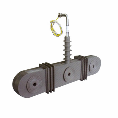
The ZW-10 is a 11kV (IEC-rated) / 10kV (domestic system equivalent) cast-resin insulated current transformer engineered for high-reliability metering and protective relaying in medium-voltage power distribution networks. Designed in strict accordance with IEC 61869-2 and GB/T 20840.2, this instrument transformer leverages advanced vacuum pressure impregnation (VPI) epoxy resin technology to deliver exceptional dielectric strength, environmental resilience, and long-term operational stability. Unlike traditional oil-immersed CTs, the ZW-10 eliminates fire hazards, oil leakage risks, and maintenance-intensive sealing systems, making it ideal for both indoor switchgear and outdoor substation applications.
Operating Principle of Cast-Resin Insulation
Cast-resin insulation in the ZW-10 employs a two-component cycloaliphatic epoxy resin system cured under vacuum and pressure (VPI process). This technique fully encapsulates the primary conductor, secondary windings, and magnetic core—typically fabricated from grain-oriented electrical steel (GOES)—within a homogeneous, void-free dielectric matrix. The absence of air pockets or moisture ingress pathways ensures consistent partial discharge performance below 10 pC at 1.2 × Um/√3 (where Um = 12 kV for 11kV systems). The resin’s high tracking resistance (CTI > 600 V) and UV-stabilized formulation enable reliable operation in polluted or coastal environments without degradation over decades of service.
Advantages Over Oil-Immersed Designs
Compared to oil-filled counterparts, the ZW-10 offers significant technical and safety advantages. Its solid insulation eliminates flammability concerns, satisfying stringent fire codes in urban substations and industrial facilities. The hermetic seal inherent to cast-resin construction prevents moisture absorption—a common cause of dielectric failure in oil units—resulting in stable insulation resistance (>10,000 MΩ at 20°C) throughout its lifecycle. Additionally, the compact mechanical design reduces footprint by up to 30%, facilitates easier handling during installation, and withstands seismic loads up to 0.5g without performance degradation. Thermal stability is enhanced through uniform heat dissipation across the resin body, maintaining accuracy even under continuous 1.2× rated current loading.
Typical Applications Overview
The ZW-10 is deployed across diverse 10/11kV infrastructure where precision and reliability are non-negotiable. Primary use cases include revenue metering at utility feeders, differential protection in ring-main units, ground-fault detection in industrial motor control centers, and harmonic monitoring in renewable integration points. Its dual-winding configuration (e.g., 0.5/5P20) simultaneously supports Class 0.5 metering accuracy and 5P20 protection class performance, enabling single-device solutions that reduce panel complexity and lifecycle costs. The transformer’s robustness against transient overvoltages (BIL 75 kV) and thermal short-time withstand capability (25 kA/1s) make it suitable for fault-prone distribution feeders.
Technical Specifications
The ZW-10 adheres to precise engineering parameters defined by IEC 61869-2 and GB/T 20840.2, ensuring interoperability and predictable performance across global installations.
| Parameter | Value |
|---|---|
| Rated Voltage (Ur) | 11 kV (IEC), 10 kV (domestic) |
| Highest Voltage (Um) | 12 kV |
| Primary Current (Ip) | 50–3000 A (standard); custom up to 4000 A |
| Secondary Current (Is) | 1 A or 5 A |
| Accuracy Classes | Metering: 0.2S, 0.5S, 0.2, 0.5 Protection: 5P10, 5P20, 10P10, 10P20 |
| Rated Output (VA) | 2.5–30 VA per winding (e.g., 15 VA @ 0.5 class) |
| Insulation Level | Power Frequency Withstand: 28 kV rms/1 min Lightning Impulse Withstand: 75 kV peak |
| Short-Time Thermal Current | 25 kA for 1 s (Ith) |
| Dynamic Withstand Current | 62.5 kA peak (Idyn) |
| Ambient Temperature Range | –40°C to +40°C |
| Altitude Limit | ≤ 1000 m (derating required above) |
| Relative Humidity | Up to 95% non-condensing |
Standard Service Conditions
The ZW-10 is rated for standard service conditions per IEC 60060-1: ambient temperature between –40°C and +40°C, relative humidity ≤95% (non-condensing), and installation altitude not exceeding 1000 meters above sea level. At altitudes above 1000 m, the dielectric strength must be derated by 1% per 100 m increment; for example, at 2000 m, the power frequency withstand voltage becomes 25.2 kV rms. The transformer maintains accuracy within ±0.2% for metering classes and ±1% for protection classes across the full temperature range due to low thermal expansion coefficient (α ≈ 60 × 10–6/K) of the epoxy resin matrix.
Core and Winding Construction
The magnetic circuit utilizes high-permeability GOES laminations (M4 grade, thickness 0.3 mm) annealed to minimize hysteresis losses and core remanence. Secondary windings are wound with oxygen-free copper (OFC) wire, insulated with Class F (155°C) enamel, and embedded directly into the resin during casting to prevent movement under electromagnetic forces. Each winding is individually tested for inter-turn insulation integrity at 3 kV rms for 1 minute. The primary conductor is either a solid copper bar (for ≤1250 A) or a multi-strand flexible cable (for >1250 A) to accommodate thermal expansion without inducing mechanical stress on the resin body.
Typical Applications
The ZW-10’s dual-certification (IEC and GB) and robust design enable deployment across varied grid architectures.
Substation Secondary Metering
In 11kV/0.4kV distribution substations, the ZW-10 provides Class 0.2S or 0.5S accuracy for revenue-grade energy metering at the HV side. Installed on outgoing feeders, it interfaces with digital meters via shielded twisted-pair cables (e.g., Belden 8761), ensuring compliance with EN 50160 voltage quality standards. The low phase displacement error (<±10 minutes at 100% In) minimizes reactive energy measurement uncertainty, critical for tariff calculations in deregulated markets. Its compact dimensions (e.g., 220 mm height × 180 mm width) allow retrofitting into legacy switchgear without busbar modifications.
Industrial Power Distribution
Within manufacturing plants, the ZW-10 supports motor protection schemes using 5P20-class windings connected to numerical relays (e.g., Siemens 7SJ62). During motor start-up surges (6–8× In), the core remains unsaturated due to optimized knee-point voltage (>150 V at 5 A secondary), ensuring accurate fault discrimination. In arc-furnace or welding facilities with high harmonic distortion (THD >15%), the transformer’s low leakage reactance (<0.5 Ω) preserves waveform fidelity for harmonic analysis systems.
Renewable Energy Integration
At solar PV or wind farm collection points, the ZW-10 monitors bidirectional power flow and detects islanding conditions. Its symmetrical saturation characteristics ensure identical accuracy during export (generation) and import (consumption) modes. For anti-islanding relays requiring <2% current error at 20% In, the 0.5S class meets IEEE 1547-2018 requirements. The resin’s hydrophobic surface repels dust accumulation in desert or agricultural settings, maintaining creepage distance (≥240 mm for 11kV).
Rural and Suburban Distribution Networks
In overhead-line rural grids prone to lightning strikes, the ZW-10’s 75 kV BIL rating withstands induced surges without external arresters in moderate-risk zones (keraunic level <30 days/year). For underground cable networks in suburban areas, its moisture-resistant design prevents degradation in manholes with standing water. Dual-ratio models (e.g., 400/1 A and 800/1 A via tap-changing) accommodate seasonal load variations without hardware replacement, reducing OPEX for utilities.
Compliance with International Standards
The ZW-10 is certified to IEC 61869-2:2012 (Instrument transformers – Part 2: Additional requirements for current transformers) and GB/T 20840.2-2014 (identical adoption of IEC 61869-2 in China), ensuring global acceptance.
IEC 61869-2 Compliance Details
Key IEC 61869-2 requirements met include: composite error ≤5% for 5P class at rated accuracy limit factor (ALF); ratio error within ±0.2% for 0.2S class at 20–120% In; and phase displacement ≤±10 minutes for 0.5 class. The transformer undergoes type tests per Clause 7: temperature rise test (Δθ ≤60 K for windings), short-circuit withstand test (25 kA/1s), and impulse voltage test (75 kV peak, 1.2/50 μs wave). Routine tests include turns ratio verification (tolerance ±0.25%) and insulation resistance measurement (>5000 MΩ at 25°C).
GB/T 20840.2 Alignment and Regional Adaptations
While GB/T 20840.2 mirrors IEC 61869-2 structurally, Chinese utilities often specify additional requirements: higher pollution degree (III vs. II), extended thermal endurance (31.5 kA/3s for urban grids), and mandatory third-party certification from CEPREI or CESI. The ZW-10 incorporates these via thicker resin walls (creepage distance ≥310 mm) and reinforced core clamping. Notably, GB standards permit 10kV nominal voltage labeling, whereas IEC mandates 11kV—both are accommodated through dual-rating plates.
Testing and Certification Protocols
Certification requires witnessed testing at accredited labs (e.g., KEMA, SGS). Critical procedures include: partial discharge measurement at 1.2 × 12/√3 kV (limit: 10 pC); power frequency withstand at 28 kV rms for 1 min (no flashover); and accuracy verification across burden range (2.5–30 VA). Each unit receives a unique test report traceable to ISO/IEC 17025, with data archived for 10 years.
On-Site Testing Procedures
Post-installation verification ensures the ZW-10 performs within specifications before energization.
Insulation Resistance Test
Using a 2500 V DC megohmmeter, measure insulation resistance between primary-to-secondary, primary-to-ground, and secondary-to-ground. Acceptance criterion: ≥10,000 MΩ at 20°C. Correct for temperature using RT2 = RT1 × 2(T1–T2)/10. Values below 1000 MΩ indicate moisture ingress or resin cracking, requiring drying or replacement.
Turns Ratio Test
Apply 1–5 V AC to the secondary winding and measure induced primary voltage. Calculate ratio as Vp/Vs. Tolerance: ±0.25% of nameplate ratio. For a 600/5 A CT, measured ratio must be 120 ±0.3. Deviations >0.5% suggest turn shorts or open circuits.
Polarity Test
Connect a 1.5 V battery between P1 and P2. Momentarily close the circuit while monitoring a DC voltmeter across S1 and S2. A positive deflection confirms subtractive polarity (standard for IEC). Incorrect polarity causes relay misoperation—recheck wiring if deflection is negative.
Power Frequency Withstand Voltage Test
Apply 28 kV rms at 50 Hz between primary and grounded secondary/enclosure for 1 minute. Use a calibrated test transformer with overcurrent trip (≤100 mA). Any flashover, smoke, or sustained current rise (>10 mA) constitutes failure. Perform only after insulation resistance exceeds 5000 MΩ.
Short-Circuit Test (for CT)
Short the secondary terminals and apply primary current at 10–20% In. Measure secondary current; ratio error must be within ±0.5%. This verifies core linearity under near-short conditions. Never leave secondary open during primary energization—risk of lethal voltage (>3 kV) and core damage.
Preventive Maintenance Guide
Proactive maintenance extends service life beyond 30 years.
Periodic Inspection Protocol
Annual visual checks include: resin surface for cracks/UV degradation; terminal tightness (torque: 12 N·m for M6 bolts); and corrosion on mounting hardware. Clean with isopropyl alcohol if salt or carbon deposits exceed 0.1 mg/cm². Infrared thermography should show ΔT <10 K between phases under load. Record insulation resistance yearly; a 50% drop from baseline warrants investigation.
Maintenance Intervals and Fault Diagnosis
Every 5 years, perform full electrical tests (ratio, polarity, insulation). Common faults: open secondary (causes ratio drift), core saturation (from DC offset), and moisture ingress (low IR). If ratio error exceeds 1%, inspect for turn-to-turn shorts via bridge measurement. Replace if partial discharge exceeds 20 pC at operating voltage.
| Interval | Action |
|---|---|
| Annually | Visual inspection, IR thermography, insulation resistance |
| 5 Years | Full electrical tests, cleaning, torque verification |
| 10 Years | Partial discharge measurement, core remanence check |
Conclusion
The ZW-10 11kV cast-resin current transformer represents a benchmark in medium-voltage instrumentation, combining IEC 61869-2 and GB/T 20840.2 compliance with field-proven reliability. Its VPI epoxy resin encapsulation eliminates the fire and environmental risks associated with oil-filled designs, while the GOES core ensures metrological stability across temperature extremes and harmonic-rich environments. With dual-winding configurations supporting simultaneous metering (Class 0.2S/0.5S) and protection (5P/10P) functions, the ZW-10 reduces system complexity and lifecycle costs in substations, industrial plants, and renewable integration points. Rigorous type testing—including 25 kA short-circuit withstand and 75 kV impulse voltage resilience—guarantees performance under fault conditions. When maintained per the recommended schedule, the ZW-10 delivers an expected service life of 25–30 years, making it a technically and economically optimal choice for modern 10/11kV distribution infrastructure demanding precision, safety, and longevity.
Frequently Asked Questions (FAQ)
Q1: Can the ZW-10 be installed outdoors without a weatherproof enclosure?
A: Yes. The cycloaliphatic epoxy resin is UV-stabilized and hydrophobic, meeting IP54 ingress protection when mounted vertically. However, in coastal areas (salt fog), periodic cleaning is advised to maintain creepage distance.
Q2: What is the maximum allowable secondary burden for a 0.5 class winding?
A: The burden must not exceed the rated output (e.g., 15 VA). Exceeding this increases ratio error; for 5 A secondary, max impedance = 15 VA / (5 A)2 = 0.6 Ω.
Q3: Is the ZW-10 compatible with legacy electromechanical relays?
A: Yes. Its 5P20 class provides sufficient accuracy for induction-disk relays, though modern numerical relays better utilize its low phase error.
Q4: How do I verify polarity during installation?
A: Use the battery-and-millivoltmeter method described in Section 5.3. Ensure P1 faces source direction; incorrect polarity reverses relay operation.
Q5: Can the primary conductor be replaced in the field?
A: No. The primary is integral to the cast-resin body. Select the correct primary rating during ordering.
Q6: What altitude derating applies above 1000 m?
A: Reduce power frequency withstand voltage by 1% per 100 m. At 2000 m, test at 25.2 kV instead of 28 kV.
Q7: Are spare secondary windings required to be shorted?
A: Yes. Always short unused secondaries with a dedicated link to prevent dangerous open-circuit voltages.
Q8: Does the ZW-10 support digital output (e.g., IEC 61850-9-2)?
A: No. It is an analog CT. For digital output, consider our ZW-10-D series with integrated merging units.