Article Content
21kV Cast-Resin Voltage Transformer JLS-20K for Metering and Protection – IEC 61869-3 Standard
Introduction to the JLS-20K Voltage Transformer
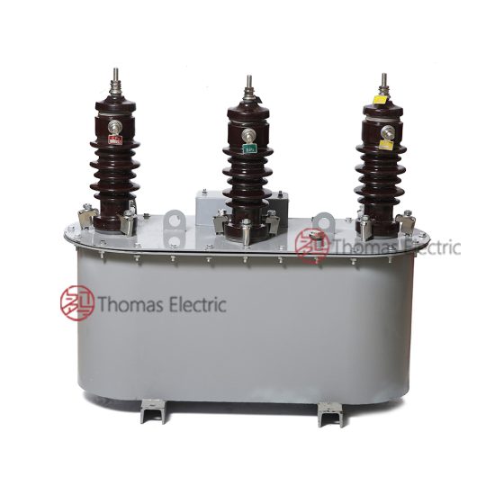
The JLS-20K is a single-phase, indoor/outdoor-rated cast-resin voltage transformer (VT) engineered for precise voltage transformation in medium-voltage (MV) power systems operating at a nominal system voltage of 20 kV, with an IEC-standard rated primary voltage of 21 kV. Designed in strict accordance with IEC 61869-3 and GB/T 20840.3, this instrument transformer provides standardized secondary outputs—typically 100 V or 110 V—for interfacing with revenue metering devices, protective relays, and power quality monitoring equipment. Its robust construction ensures long-term stability under continuous electrical stress, thermal cycling, and environmental exposure.
Operating Principle of Cast-Resin Insulation
Cast-resin insulation in the JLS-20K employs vacuum pressure impregnation (VPI) technology using cycloaliphatic epoxy resin systems. The primary and secondary windings are wound on high-permeability grain-oriented electrical steel (GOES) cores and then fully encapsulated under vacuum to eliminate air voids and moisture ingress. This monolithic structure provides superior dielectric strength, tracking resistance, and mechanical rigidity compared to traditional oil-paper or dry-wound designs. The resin’s high glass transition temperature (>120°C) ensures dimensional stability across the full operational temperature range (-40°C to +40°C ambient). Partial discharge levels are maintained below 10 pC at 1.2 × Um/√3, as required by IEC 61869-3, ensuring minimal aging and extended service life.
Advantages Over Oil-Immersed Designs
Unlike oil-immersed VTs, the JLS-20K eliminates fire hazards, environmental contamination risks, and maintenance-intensive oil sampling. Its solid insulation requires no periodic topping-up or degassing, making it ideal for indoor substations, urban switchgear rooms, and environmentally sensitive zones. The absence of liquid also reduces weight by approximately 30% and simplifies transportation and handling. Furthermore, cast-resin VTs exhibit faster thermal response during transient overvoltages and better resistance to seismic loads due to their rigid composite structure. These attributes make the JLS-20K particularly suitable for compact secondary substations and prefabricated modular units where space and safety are critical constraints.
Typical Applications Overview
The JLS-20K is deployed across diverse MV infrastructure, including utility distribution substations (20/0.4 kV), industrial plant switchyards, renewable energy collector systems (e.g., solar farms with 20 kV collection grids), and railway traction networks. It supports both metering-class (0.2, 0.5) and protection-class (3P, 6P) burdens simultaneously via dual secondary windings. In smart grid applications, its stable ratio error (<±0.2% at 80–120% of rated voltage) enables accurate billing and demand-side management. The transformer’s design accommodates direct mounting on ring-main units (RMUs) or withdrawable switchgear, facilitating rapid integration into modern digital substation architectures compliant with IEC 61850.
Technical Specifications
The JLS-20K is engineered to meet stringent performance criteria under defined service conditions. All parameters align with IEC 61869-3 (2011) and GB/T 20840.3 (2013) requirements for electromagnetic voltage transformers.
| Parameter | Value |
|---|---|
| Rated Primary Voltage (Up) | 21 kV (IEC), 20 kV (domestic system) |
| Rated Secondary Voltage (Us) | 100 V or 110 V (standard); 100/√3 V for phase-to-earth systems |
| Voltage Ratio | 21000/100 V, 21000/110 V, or 21000/√3 : 100/√3 V |
| Accuracy Class | Metering: 0.2, 0.5; Protection: 3P, 6P |
| Rated Output (per winding) | 10–100 VA (configurable per burden requirement) |
| Insulation Level (LI/AC) | 170 kV / 70 kV (per IEC 60071-1) |
| Short-Time Thermal Withstand | 1 s at 25× rated current (secondary short-circuit) |
| Core Material | Grain-Oriented Electrical Steel (GOES), 0.27 mm lamination |
| Insulation System | Cycloaliphatic epoxy resin, VPI process |
| Ambient Temperature Range | -40°C to +40°C |
| Altitude Limit | ≤1000 m (derating required above 1000 m) |
| Relative Humidity | ≤95% non-condensing |
Standard Service Conditions
The JLS-20K is rated for standard service conditions as defined in IEC 61869-1: ambient temperature between -40°C and +40°C, relative humidity up to 95% without condensation, and installation altitude not exceeding 1000 meters above sea level. At altitudes above 1000 m, the dielectric withstand voltage must be derated by 1% per 100 m increment. The transformer is designed for continuous operation at 1.2 × Un under normal load and can withstand temporary overvoltages up to 1.9 × Un for 8 hours without degradation. Installation in polluted environments (e.g., coastal or industrial zones) requires adherence to creepage distance specifications: ≥25 mm/kV for pollution class II, ≥31 mm/kV for class III.
Electrical Performance Parameters
Ratio error and phase displacement are tightly controlled across the operating range. For a 0.2-class metering winding, ratio error must remain within ±0.2% and phase error within ±10 minutes at 20–100% of rated voltage and 25–100% of rated burden. Protection windings (3P) maintain ratio error ≤±3% and phase error ≤±120 minutes under fault conditions (5–100% of rated voltage). The magnetizing current at rated voltage is typically <0.5% of rated primary current, minimizing loading effects on the primary circuit. Thermal stability is verified through a 4-hour temperature rise test: winding temperature rise ≤60 K above ambient when loaded at 1.5 × rated output.
Typical Applications
The JLS-20K serves as a foundational component in modern MV power systems requiring reliable, maintenance-free voltage sensing.
Substation Secondary Metering
In 20 kV/0.4 kV distribution substations, the JLS-20K provides accurate voltage input to revenue-class kWh meters and power quality analyzers. Its dual secondary windings allow one output (0.2 class) to feed billing meters while another (0.5 class) supplies SCADA RTUs or local HMI panels. The transformer’s low phase error ensures correct calculation of reactive energy and power factor, critical for utility tariff compliance. Installation on the HV side of the main incomer switchgear enables real-time monitoring of grid voltage stability and harmonic distortion (THD <3% up to 13th order).
Industrial Power Distribution
Large manufacturing facilities with internal 20 kV distribution networks use the JLS-20K for motor protection, capacitor bank control, and arc-flash mitigation systems. In steel mills or chemical plants, its flame-retardant resin housing meets IEC 60695 flammability standards, eliminating explosion risks in hazardous areas. The VT interfaces directly with numerical relays (e.g., Siemens 7SJ, SEL-351) to enable undervoltage tripping, overvoltage alarms, and vector-jump detection during islanding events. Its compact footprint allows retrofitting into legacy switchgear without panel modifications.
Renewable Energy Integration
Solar photovoltaic (PV) farms often employ 20 kV collector systems feeding into step-up transformers. The JLS-20K monitors grid voltage at the point of interconnection (POI) to comply with IEEE 1547 or GB/T 19964 anti-islanding requirements. During cloud transients, its fast response time (<20 ms) ensures accurate ride-through voltage measurement for inverter control. In wind farms, it supports synchro-check relaying during turbine reconnection after grid faults. The transformer’s immunity to DC offset and harmonics makes it suitable for inverters with non-sinusoidal output waveforms.
Rural and Suburban Distribution Networks
In remote or semi-urban areas with limited maintenance access, the JLS-20K’s sealed, dry-type design offers significant lifecycle cost advantages. Mounted on pole-top platforms or pad-mounted switchgear, it enables remote voltage regulation via automatic tap changers (AVRs) and supports outage management systems (OMS) through consistent telemetry. Its resistance to UV radiation and thermal cycling ensures reliability in regions with diurnal temperature swings exceeding 50°C. Utilities report >99.5% availability over 10-year deployments in such environments.
Compliance with International Standards
The JLS-20K is certified to both international and Chinese national standards, ensuring global interoperability and regulatory acceptance.
IEC 61869-3 Compliance Details
IEC 61869-3 specifies performance, testing, and marking requirements for inductive voltage transformers. The JLS-20K undergoes type tests including temperature rise, short-circuit withstand, impulse voltage (1.2/50 µs), and partial discharge measurements. Routine tests include ratio verification (±0.1% tolerance), polarity check (reducing polarity confirmed), and power frequency withstand (70 kV rms for 1 min). The transformer’s nameplate includes mandatory markings: rated voltages, accuracy classes, burden values, serial number, and manufacturer identification per Clause 10 of IEC 61869-3. Environmental testing per IEC 60068 confirms operation after thermal shock (-25°C to +55°C, 5 cycles).
Alignment with GB/T 20840.3
GB/T 20840.3 mirrors IEC 61869-3 but includes supplementary requirements for the Chinese market, such as stricter partial discharge limits (<5 pC at 1.2 × Um/√3) and mandatory seismic qualification (horizontal acceleration 0.25g). The JLS-20K complies with all clauses, including those governing insulation coordination for 20 kV systems (Um = 24 kV). Domestic certification by CEPREI or SGS China validates conformance, enabling procurement by State Grid and China Southern Power Grid. Notably, GB/T 20840.3 mandates dual secondary windings for combined metering/protection use—a feature standard on the JLS-20K.
Key Differences Between IEC and Domestic Standards
While IEC 61869-3 permits single secondary windings for dedicated applications, GB/T 20840.3 requires dual windings for all new installations to separate metering and protection circuits—a critical safety measure against relay-induced metering errors. Additionally, Chinese standards specify higher creepage distances (≥31 mm/kV vs. IEC’s 25 mm/kV) for coastal regions. The JLS-20K’s design incorporates these enhanced requirements by default, ensuring seamless deployment in both domestic and export markets. Testing protocols also differ: GB/T mandates 100% routine partial discharge testing, whereas IEC allows sampling.
On-Site Testing Procedures
Post-installation verification ensures the JLS-20K performs within specification before energization.
Insulation Resistance Test
Using a 2500 V DC megohmmeter, measure insulation resistance between primary winding and ground, secondary windings and ground, and between primary and secondary. Acceptance criteria: ≥1000 MΩ at 20°C. Correct for temperature using RT2 = RT1 × 2(T1-T2)/10. Values below 500 MΩ indicate moisture ingress or resin cracking and require drying or replacement. Perform before and after power frequency withstand tests to detect insulation degradation.
Turns Ratio Test
Apply a low-voltage AC source (50–100 V) to the primary and measure secondary voltage with a calibrated voltmeter. Calculate actual ratio and compare to nameplate. Tolerance: ±0.1% for metering windings, ±0.5% for protection windings. Use a ratio bridge (e.g., Omicron CT Analyzer) for precision. Deviations beyond tolerance suggest turn-to-turn shorts or incorrect tapping—requiring factory return.
Polarity Test
Verify reducing polarity using the DC kick method: connect a 6–12 V battery to primary terminals (H1+, H2−) and observe secondary voltage deflection on a center-zero galvanometer connected to X1, X2. A momentary positive kick confirms correct polarity. Incorrect polarity causes 180° phase reversal, leading to metering errors or relay misoperation. Document results with timestamped oscillograms for commissioning records.
Power Frequency Withstand Voltage Test
Apply 70 kV rms at 50 Hz between primary and ground (with secondaries shorted and grounded) for 1 minute. Monitor for flashover, excessive leakage current (>1 mA), or audible discharge. The test verifies insulation integrity after transport and installation stresses. Conduct only after successful insulation resistance and ratio tests. Use a calibrated test transformer with overcurrent protection set at 100 mA.
Open-Circuit Characteristic Test
With secondary open, gradually increase primary voltage from 20% to 120% of rated value while recording excitation current. Plot V-I curve: knee point should occur above 110% Un. Excessive magnetizing current (>1% of rated) indicates core saturation or interlamination shorts. This test validates core quality and detects residual mechanical stress from casting.
Preventive Maintenance Guide
Although cast-resin VTs require minimal maintenance, periodic checks ensure decades of reliable service.
Periodic Inspection Protocol
Conduct visual and thermographic inspections annually. Check for surface tracking, UV discoloration, terminal corrosion, or mechanical damage. Use infrared imaging to detect abnormal heating at connections (>10 K above ambient indicates loose bolts or oxidation). Clean housing with non-abrasive detergent; avoid solvents that degrade resin. Verify grounding continuity (<0.1 Ω resistance). Record findings in asset management software for trend analysis.
Maintenance Intervals and Fault Diagnosis
Replace only if insulation resistance drops below 200 MΩ persistently after cleaning, or if ratio error exceeds twice the initial commissioning value. Common failure modes include: (1) terminal block cracking due to overtightening—repair with epoxy putty; (2) moisture ingress at secondary gland—re-seal with IP66-rated cable glands; (3) core delamination from severe overvoltage—requires replacement. No internal servicing is permitted; the unit is hermetically sealed.
| Interval | Action |
|---|---|
| Annual | Visual inspection, IR thermography, grounding check |
| 5 Years | Insulation resistance, ratio verification, open-circuit test |
| After Major Fault | Full suite of on-site tests (Sections 5.1–5.5) |
Conclusion
The JLS-20K 21kV cast-resin voltage transformer represents a benchmark in reliability, accuracy, and compliance for medium-voltage applications. By leveraging advanced VPI epoxy resin technology and GOES core materials, it delivers exceptional dielectric performance, thermal stability, and environmental resilience—outperforming legacy oil-filled alternatives in safety and lifecycle cost. Its dual-winding architecture supports simultaneous metering (0.2/0.5 class) and protection (3P/6P) functions with minimal cross-interference, ensuring regulatory compliance across global markets. Certified to both IEC 61869-3 and GB/T 20840.3, the JLS-20K meets the most stringent international and domestic requirements for accuracy, insulation coordination, and seismic robustness. With a design service life of 25–30 years under standard operating conditions, it offers utilities and industrial operators a future-proof solution for grid modernization, renewable integration, and smart substation deployment. Proper installation and adherence to the outlined testing and maintenance protocols further guarantee decades of trouble-free operation, making the JLS-20K a cornerstone of dependable MV instrumentation infrastructure.
Frequently Asked Questions (FAQ)
Q1: Can the JLS-20K be installed outdoors without additional housing?
Yes. The JLS-20K features UV-stabilized cycloaliphatic resin and IP54-rated terminals, permitting direct outdoor mounting on poles or switchgear. However, in heavy pollution zones (IEC 60815 class III/IV), consider adding silicone rubber sheds or installing under a canopy.
Q2: What is the maximum allowable secondary burden for a 0.2-class winding?
The rated output defines the maximum burden. For example, a 30 VA 0.2-class winding must not exceed 30 VA total burden (including meter impedance, lead resistance, and relay coils). Exceeding this degrades accuracy beyond ±0.2%.
Q3: Is it permissible to leave the secondary winding open during operation?
No. While VTs can operate with open secondaries unlike CTs, prolonged open-circuit operation increases core flux density, raising magnetizing current and risk of overheating. Always terminate unused windings with a shorting link or dummy load.
Q4: How does altitude affect the JLS-20K’s insulation withstand capability?
Above 1000 m, reduce the power frequency withstand voltage by 1% per 100 m. At 2000 m, the 70 kV test becomes 63 kV. Consult IEC 60071-2 for detailed correction factors.
Q5: Can the JLS-20K be used in ungrounded (isolated neutral) 20 kV systems?
Yes, provided the system’s maximum earth-fault duration complies with IEC 61869-3 Annex B. The transformer must withstand 1.9 × Un for 8 hours during single-line-to-ground faults.
Q6: What torque should be applied to the primary terminal bolts?
Use 25 N·m for M12 copper-alloy terminals. Over-torquing (>30 N·m) risks cracking the resin bushing; under-torquing increases contact resistance and heating.
Q7: Are there special requirements for secondary cabling?
Use shielded twisted-pair cable (min. 2.5 mm² Cu) with shield grounded at one end only (typically at relay panel) to prevent ground loops. Maximum loop resistance should not exceed 0.1 Ω for 0.2-class applications.