Article Content
33kV Cast-Resin Voltage Transformer JLS-35K for Metering and Protection – IEC 61869-3 Standard
Introduction to the JLS-35K Voltage Transformer
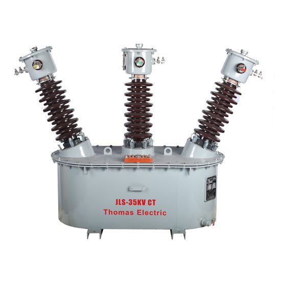
The JLS-35K is a precision-engineered, cast-resin insulated voltage transformer (VT) designed for reliable operation in 33kV (IEC standard) or 35kV (domestic Chinese system) medium-voltage networks. As a critical interface between high-voltage primary circuits and low-voltage secondary instrumentation, it enables accurate voltage measurement, energy metering, and protective relay coordination in utility substations, industrial plants, and renewable energy facilities. Unlike legacy oil-immersed designs, the JLS-35K leverages advanced vacuum pressure impregnation (VPI) epoxy resin technology to deliver superior dielectric strength, environmental resilience, and maintenance-free operation over its 25–30 year service life.
Operating Principle of Cast-Resin Insulation
Cast-resin insulation in the JLS-35K employs a two-component cycloaliphatic epoxy resin system cured under vacuum and pressure to eliminate voids and moisture ingress. The primary and secondary windings—wound with high-purity electrolytic copper—are fully encapsulated within this solid dielectric matrix, which provides uniform electric field distribution and prevents partial discharge activity even under transient overvoltages. The resin’s high tracking resistance (>600 V per IEC 60587) ensures long-term surface stability in polluted environments. Thermal conductivity of ~0.8 W/m·K allows efficient heat dissipation from the GOES (grain-oriented electrical steel) core, maintaining stable accuracy across load cycles. This monolithic structure eliminates the fire hazard, leakage risks, and periodic oil testing associated with liquid-filled transformers, making it ideal for indoor switchgear and urban substations where safety and space constraints are paramount.
Advantages Over Oil-Immersed Designs
Compared to traditional oil-immersed VTs, the JLS-35K offers significant operational and safety benefits. Its dry-type construction eliminates flammability concerns, satisfying stringent fire codes in commercial and industrial facilities. The absence of oil also removes the need for conservator tanks, breather systems, and oil sampling—reducing lifecycle costs by up to 40% over 25 years. Mechanically, the rigid epoxy housing provides excellent vibration damping, minimizing microphonic noise and winding displacement during short-circuit events. Furthermore, the compact footprint (typically 30% smaller than equivalent oil units) facilitates retrofitting into existing switchgear bays without structural modifications. Environmental compliance is enhanced as the unit contains no PCBs or hazardous liquids, simplifying end-of-life disposal per RoHS and WEEE directives. These attributes make the JLS-35K the preferred choice for modern smart substations prioritizing reliability, sustainability, and minimal maintenance.
Typical Application Overview
The JLS-35K is deployed across diverse power infrastructure segments requiring precise voltage transformation with high reliability. In utility transmission substations, it feeds metering circuits for revenue-grade kWh measurement and supplies voltage inputs to distance relays for line protection. Industrial customers use it in 35kV distribution feeders to monitor power quality and enable automatic load shedding during undervoltage conditions. Renewable integration projects—particularly solar farms with 35kV collector systems—rely on its stable ratio accuracy to synchronize inverters and comply with grid code requirements (e.g., GB/T 19964). Rural electrification schemes benefit from its robustness against humidity and dust, ensuring consistent performance in unattended locations. Each application leverages the transformer’s dual secondary windings (e.g., 0.2/3P accuracy classes) to simultaneously serve metering and protection functions without cross-interference.
Technical Specifications
The JLS-35K is engineered to meet exacting electrical and environmental parameters defined by IEC 61869-3 and GB/T 20840.3. Below is a comprehensive specification table followed by detailed service condition requirements.
| Parameter | Value |
|---|---|
| Primary Voltage (IEC) | 33 kV / √3 |
| Primary Voltage (Domestic) | 35 kV / √3 |
| Secondary Voltage | 100 V / √3 (standard); 110 V / √3 (optional) |
| Voltage Ratio | (33,000/√3) : (100/√3) = 330:1 |
| Accuracy Class (Metering) | 0.2 (per IEC 61869-3) |
| Accuracy Class (Protection) | 3P (composite error ≤ 3% at 5%–100% rated voltage) |
| Rated Output (Burden) | 30 VA (metering), 50 VA (protection) |
| Insulation Level (LI/AC) | 170 kV / 70 kV (per IEC 60071-1) |
| Short-Time Thermal Withstand | 1.2 × rated voltage for 30 s |
| Core Material | GOES (Grain-Oriented Electrical Steel), 0.27 mm thickness |
| Insulation System | VPI Epoxy Resin, Class F (155°C) |
| Phase Displacement | ≤ ±10 minutes (at 0.2 class) |
| Ratio Error Tolerance | ±0.2% (metering), ±3.0% (protection) |
Standard Service Conditions
The JLS-35K is rated for continuous operation under the following ambient conditions per IEC 60060-1 and GB/T 11022: ambient temperature range of –25°C to +40°C (with derating above +40°C), relative humidity up to 95% non-condensing, and installation altitude not exceeding 1,000 meters above sea level. For sites above 1,000 m, insulation levels must be adjusted per IEC 60071-2 (e.g., +1% LI per 100 m above 1,000 m). The unit is suitable for both indoor and outdoor installation when housed in IP23-rated enclosures; direct exposure to UV radiation requires optional UV-stabilized resin formulation. Pollution severity is classified as Class III (medium) per IEC 60815, with creepage distance ≥25 mm/kV RMS. These parameters ensure stable performance in coastal, desert, and high-humidity regions common in Southeast Asia and Southern China.
Electrical Performance Characteristics
Key electrical behaviors include a magnetizing current of ≤0.5% of rated primary current at nominal voltage, ensuring minimal loading on the primary circuit. The knee-point voltage exceeds 1.9 × rated secondary voltage, providing adequate saturation margin during fault conditions. Transient response meets IEC 61869-3 Annex D requirements, with peak overvoltage during switching surges limited to 1.5 p.u. for durations under 10 ms. Temperature rise under full burden is ≤60 K above ambient, verified via thermal imaging during type tests. Partial discharge magnitude is maintained below 10 pC at 1.2 × Um/√3, confirming void-free resin encapsulation. These characteristics guarantee metrological integrity for billing applications and dependable relay operation during system disturbances.
Typical Applications
The JLS-35K serves as a foundational component in modern power systems where accuracy, safety, and longevity are non-negotiable. Its dual-winding configuration supports concurrent metering and protection functions without compromise.
Substation Secondary Metering
In 35kV utility substations, the JLS-35K’s 0.2-class secondary winding interfaces directly with revenue meters (e.g., IEC 62053-22 compliant) to record energy consumption with ±0.2% error tolerance. This precision is critical for tariff reconciliation between generation, transmission, and distribution entities. The transformer’s low phase displacement (<10 arcminutes) ensures accurate power factor calculation, while its stable ratio over temperature minimizes seasonal billing discrepancies. Installation typically occurs on the busbar side of circuit breakers, with secondary cabling routed through shielded conduits to mitigate electromagnetic interference from adjacent CTs. Compliance with GB/T 20840.3 ensures interoperability with Chinese national metering infrastructure.
Industrial Power Distribution
Large manufacturing complexes—such as steel mills or petrochemical plants—deploy the JLS-35K on 35kV feeders to monitor voltage sags, swells, and harmonics that could disrupt sensitive processes. The 3P-class protection winding supplies inputs to undervoltage relays (e.g., IEC 60255-151) that trigger motor shutdown sequences during grid instability. Its cast-resin construction withstands mechanical vibrations from nearby heavy machinery, while the high short-time thermal rating accommodates frequent motor-starting transients. In arc furnace installations, the unit’s immunity to magnetic saturation ensures reliable operation despite severe harmonic distortion (THD up to 8%).
Renewable Energy Integration
Solar photovoltaic farms with 35kV collector systems utilize the JLS-35K to provide grid-synchronization signals to inverters per GB/T 19964-2012. The transformer’s fast transient response (<20 ms recovery after cloud-induced irradiance changes) maintains stable voltage regulation during rapid power fluctuations. Dual secondaries allow one winding to feed SCADA telemetry while the other drives anti-islanding protection relays. Outdoor-rated versions with hydrophobic resin surfaces resist soiling in dusty desert environments, preserving insulation integrity over decades of exposure.
Rural and Suburban Distribution Networks
In remote agricultural or mountainous regions, the JLS-35K’s maintenance-free design reduces operational costs for utilities managing dispersed assets. Installed on pole-top or pad-mounted switchgear, it enables remote voltage monitoring via cellular-connected RTUs. The wide operating temperature range accommodates extreme diurnal swings (e.g., –30°C nights to +45°C days in Xinjiang), while the high pollution withstand prevents flashovers during sandstorms or salt fog events. Its lightweight construction (≈85 kg) simplifies helicopter deployment in inaccessible terrain.
Compliance with International Standards
The JLS-35K is rigorously certified to both global and Chinese national standards, ensuring interoperability and regulatory acceptance across markets.
IEC 61869-3 Certification Details
As a dedicated voltage transformer, the JLS-35K complies fully with IEC 61869-3:2011 “Instrument transformers – Part 3: Additional requirements for inductive voltage transformers.” This includes mandatory type tests for temperature rise (Clause 7.3), short-circuit withstand (Clause 7.4), and accuracy verification under varying burdens (Clause 7.6). The standard mandates composite error limits for protection classes (e.g., 3P requires ≤3% error at 5%–100% Un), which the JLS-35K achieves through optimized core cross-section and low-loss GOES laminations. Dielectric tests per Clause 7.2 require 70 kV AC for 1 minute and 170 kV lightning impulse, both passed with safety margins. Certification is issued by accredited laboratories such as KEMA or CESI, with test reports traceable to BIPM standards.
Alignment with GB/T 20840.3
GB/T 20840.3-2013 (“Instrument transformers – Part 3: Additional requirements for inductive voltage transformers”) mirrors IEC 61869-3 but includes China-specific provisions. Notably, it requires extended thermal endurance testing at 1.2 × Un for 8 hours (vs. 30 minutes in IEC) to simulate prolonged overvoltage conditions common in weak rural grids. The standard also specifies stricter partial discharge limits (≤5 pC at 1.2 × Um/√3) and mandates seismic qualification for units installed in earthquake-prone zones (e.g., Sichuan province). The JLS-35K’s resin formulation incorporates nano-alumina fillers to enhance mechanical damping, achieving Zone 2 seismic rating per GB/T 13499. All production batches undergo routine tests per Clause 8, including ratio verification and polarity checks.
Key Differences Between IEC and Domestic Standards
While IEC 61869-3 focuses on universal performance criteria, GB/T 20840.3 emphasizes local grid challenges. For instance, Chinese standards require VTs to maintain accuracy during 10% voltage unbalance—a common occurrence in asymmetric rural networks—whereas IEC assumes balanced systems. Additionally, GB/T mandates dual secondary windings as standard (metering + protection), while IEC permits single-winding configurations. Environmental testing under GB/T includes salt fog exposure (96 hours per GB/T 2423.17) for coastal installations, a requirement absent in IEC. These adaptations ensure the JLS-35K meets the reliability expectations of State Grid Corporation and China Southern Power Grid.
On-Site Testing Procedures
Post-installation verification ensures the JLS-35K performs within specified tolerances before energization. All tests follow IEC 61869-3 Annex A and DL/T 726-2013 guidelines.
Insulation Resistance Test
Using a 2,500 V DC megohmmeter, measure insulation resistance between primary-to-secondary, primary-to-ground, and secondary-to-ground. Acceptance criteria: ≥1,000 MΩ at 20°C. Correct for temperature using R20 = Rt × 2(20–t)/10. Values below 500 MΩ indicate moisture ingress or resin cracking, requiring drying or replacement. Perform before and after dielectric tests to detect insulation degradation.
Turns Ratio Test
Apply 100–200 V AC to the primary winding and measure secondary voltage with a calibrated voltmeter (accuracy class 0.1). Calculate ratio as Vp/Vs; compare to nameplate value (330:1). Tolerance: ±0.2% for metering class, ±3.0% for protection class. Use a dedicated ratio bridge (e.g., Omicron CT Analyzer) for automated verification. Deviations beyond tolerance suggest inter-turn faults or incorrect tap selection.
Polarity Test
Verify reducing polarity per IEC 61869-1 Figure 3. Connect a 6–12 V battery across primary terminals (H1+, H2–). Momentarily close the circuit while monitoring secondary voltage with a DC millivoltmeter (X1+, X2–). A positive kick confirms correct polarity. Incorrect polarity causes 180° phase reversal, leading to metering errors or relay misoperation. Document results in commissioning reports.
Power Frequency Withstand Voltage Test
Apply 70 kV RMS at 50 Hz between primary and grounded secondary/enclosure for 1 minute per IEC 60060-1. Use a calibrated sphere gap or capacitive divider for voltage measurement. No flashover or disruptive discharge is permitted. Ramp voltage at 2 kV/s to avoid transient overstress. This test validates insulation integrity after transportation and installation stresses.
Open-Circuit Characteristic Test
With secondary open, gradually increase primary voltage from 20% to 120% of rated value while recording excitation current. Plot Iexc vs. Vp; the curve should show linear behavior below 100% Un and gradual saturation above. Knee-point voltage must exceed 1.9 × (100/√3) ≈ 110 V. Excessive magnetizing current (>1% rated) indicates core lamination damage or shorted turns.
Preventive Maintenance Guide
Although cast-resin VTs require minimal maintenance, periodic inspections extend service life and prevent unexpected failures.
Annual Visual and Functional Inspection
Inspect for surface cracks, tracking marks, or discoloration on the resin housing—indicative of partial discharge or UV degradation. Check terminal tightness (torque: 15 N·m for M10 bolts) and corrosion on grounding connections. Verify secondary wiring integrity and burden compatibility (total VA ≤ rated output). Clean housing with non-abrasive detergent if contaminated by salt or cement dust. Record insulation resistance annually; a 30% decline warrants further investigation.
Five-Year Comprehensive Maintenance
Every 60 months, perform partial discharge measurement using IEC 60270 methods. Acceptable level: ≤10 pC at 1.2 × Um/√3. Conduct thermal imaging under load to detect hot spots (>10 K above ambient suggests internal faults). Re-calibrate ratio and accuracy using a portable test set (e.g., Megger MIT400). Replace surge arresters connected to the VT secondary if leakage current exceeds 0.5 mA. Update maintenance logs per ISO 55001 asset management protocols.
Maintenance Intervals and Fault Diagnosis
| Interval | Action | Fault Indicators |
|---|---|---|
| Annually | Visual inspection, IR test | Cracks, >20% IR drop |
| 5 Years | PD test, thermal scan | PD >15 pC, hotspot |
| 10 Years | Full recalibration | Ratio error >0.3% |
| As needed | Burden audit | Relay misoperation |
Common failure modes include secondary winding open-circuit (causing dangerous overvoltage) and core saturation due to excessive burden. Immediate de-energization is required if abnormal humming or ozone odor is detected.
Conclusion
The JLS-35K 33kV cast-resin voltage transformer represents the convergence of international engineering standards and practical field reliability. By adhering strictly to IEC 61869-3 and GB/T 20840.3, it delivers metrological precision for revenue metering (0.2 class) and dependable performance for protection applications (3P class) across diverse environmental conditions. Its VPI epoxy resin insulation system, combined with GOES silicon steel cores, ensures maintenance-free operation for 25–30 years—even in harsh industrial or coastal settings. The elimination of flammable oils enhances safety in confined spaces, while the compact design facilitates seamless integration into modern switchgear. On-site testing protocols and preventive maintenance schedules further guarantee long-term accuracy and system compatibility. For utilities and industrial operators seeking a future-proof solution for 35kV network instrumentation, the JLS-35K provides an optimal balance of technical excellence, regulatory compliance, and lifecycle cost efficiency. Its proven track record in thousands of installations across Asia underscores its role as a cornerstone of resilient power infrastructure.