Article Content
RS-485 11kV Cast-Resin Voltage Transformer for Substation Metering and Protection – IEC 61869-3 Certified
Introduction to the RS-485 Voltage Transformer
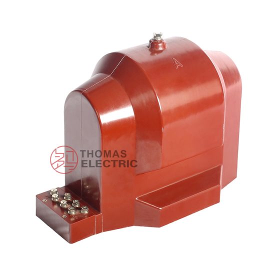
The RS-485 is a single-phase, indoor-type cast-resin voltage transformer (VT) engineered for high-accuracy voltage transformation in 11kV (IEC) / 10kV (domestic) medium-voltage power systems. Designed in strict accordance with IEC 61869-3 and GB/T 20840.3, this instrument transformer serves critical roles in revenue metering, protective relaying, and system monitoring within utility substations, industrial facilities, and renewable energy interconnection points. Its core innovation lies in vacuum pressure impregnation (VPI) epoxy resin encapsulation, which fully embeds the primary and secondary windings along with the grain-oriented electrical steel (GOES) magnetic core in a solid dielectric matrix.
Operating Principle of Cast-Resin Insulation
Cast-resin insulation in the RS-485 employs a two-component cycloaliphatic epoxy system processed under vacuum and pressure to eliminate voids and moisture ingress pathways. During manufacturing, the wound core assembly is placed in a mold, evacuated to remove air, and then injected with degassed resin under controlled pressure (typically 0.3–0.5 MPa). The curing cycle follows a precise thermal profile (e.g., 80°C for 4 hours followed by 120°C for 6 hours) to achieve full cross-linking. This results in a homogeneous, non-hygroscopic solid with a dielectric strength exceeding 20 kV/mm and a relative permittivity (εr) of approximately 3.8 at 50 Hz. Unlike oil-filled designs, the absence of liquid eliminates fire hazards, leakage risks, and maintenance-intensive oil testing. The resin’s coefficient of thermal expansion closely matches that of copper and GOES steel, minimizing mechanical stress during thermal cycling from –25°C to +40°C ambient operation.
Advantages Over Oil-Immersed Designs
Compared to traditional oil-immersed VTs, the RS-485 offers superior environmental resilience and lifecycle economics. The solid epoxy body provides IP54 ingress protection without requiring sealed tanks or conservators, making it ideal for dusty or humid indoor switchgear rooms. Fire safety is enhanced—epoxy resin is self-extinguishing (UL 94 V-0 rated) and produces no flammable vapors under fault conditions. Maintenance is reduced to visual inspections only, as there is no oil degradation, gas accumulation, or moisture absorption to monitor. Additionally, the compact footprint (typically 280 mm height × 180 mm width) allows direct mounting on 10kV busbars in ring-main units or metal-clad switchgear, saving valuable substation space. Electromagnetic performance is also improved: the tight resin encapsulation dampens magnetostriction-induced vibrations, reducing audible noise to below 45 dB(A) at rated voltage.
Typical Applications Overview
The RS-485 is deployed wherever precise, reliable voltage sensing is required in 11kV networks. Primary use cases include connection to kWh meters for billing accuracy (Class 0.2 or 0.5 per IEC 61869-3), feeding voltage inputs to overvoltage, undervoltage, and directional earth-fault relays (protection class 3P or 6P), and supplying synchrocheck or power quality analyzers. Its robust design supports continuous operation in environments with daily load swings, frequent switching transients, and harmonic distortion up to THD 5%. Common installations span urban distribution substations, cement plants with arc furnace loads, solar farms with string inverters, and railway traction feeders—all demanding long-term stability without recalibration.
Technical Specifications
The RS-485 voltage transformer delivers precision performance across defined electrical and environmental parameters. All ratings comply with IEC 61869-3:2011 and GB/T 20840.3-2013, ensuring interoperability in global and domestic grids.
| Parameter | Value |
|---|---|
| System Voltage (Um) | 11 kV (IEC) / 10 kV (GB) |
| Primary Voltage (Up) | 10 / √3 kV or 11 / √3 kV (line-to-ground) |
| Secondary Voltage (Us) | 100 / √3 V or 110 / √3 V (standard); 100 V or 110 V (line-to-line optional) |
| Voltage Ratio | (10,000 / √3) : (100 / √3) = 100:1 (typical) |
| Accuracy Class (Metering) | 0.2, 0.5 (per IEC 61869-3 Table 101) |
| Accuracy Class (Protection) | 3P, 6P (composite error ≤ 3% or 6% at rated voltage and burden) |
| Rated Output (VA) | 10, 15, 20, 30, 50 VA (selectable per application) |
| Insulation Level (LI/AC) | 75 kV lightning impulse / 28 kV power frequency (1 min) |
| Short-Time Thermal Withstand | 1 second at 100× rated primary current (for fault duty) |
| Magnetic Core Material | Grain-Oriented Electrical Steel (GOES), M4 grade, 0.27 mm thickness |
| Dielectric Loss Tangent (tan δ) | < 0.005 at 10 kV, 50 Hz |
Standard Service Conditions
The RS-485 is rated for indoor operation under standard service conditions defined in IEC 61869-1 Clause 5. Ambient temperature range is –25°C to +40°C, with a 24-hour average not exceeding +35°C. Relative humidity may reach 95% non-condensing at +25°C. Installation altitude is limited to 1,000 meters above sea level; for altitudes up to 3,000 m, derating factors per IEC 60071-1 apply (e.g., 1.13× increase in test voltage at 2,000 m). The transformer must be mounted vertically on a grounded metallic support with adequate clearance: minimum 125 mm phase-to-phase and 100 mm phase-to-ground in air. Continuous operation is permitted at 1.2× rated primary voltage for up to 8 hours per day, and 1.5× for 30 seconds during transient events.
Electrical Performance Tolerances
Voltage ratio error at rated frequency (50/60 Hz) and burden must remain within ±0.2% for Class 0.2 and ±0.5% for Class 0.5 under 25–100% of rated voltage. Phase displacement is limited to ±10 minutes (0.17°) for Class 0.2 and ±20 minutes (0.33°) for Class 0.5. For protection classes, the composite error (εc) is calculated as εc = |(KnIs – Ip) / Ip| × 100%, where Kn is the nominal ratio. At 5% of rated voltage, ratio error may widen to ±0.6% (Class 0.5) but must not exceed specified limits at 100% voltage. Burden tolerance is ±10% of declared VA rating; exceeding this degrades accuracy and may cause overheating.
Typical Applications
The RS-485 voltage transformer is engineered for diverse operational contexts where reliability, accuracy, and compactness are paramount. Below are five representative deployment scenarios.
Substation Secondary Metering
In 10kV/0.4kV distribution substations, the RS-485 provides the voltage reference for three-phase kWh meters used in commercial and industrial billing. Installed on the 10kV busbar, it feeds secondary voltages to meters via shielded twisted-pair cables (e.g., 2×1.5 mm² Cu). To meet Class 0.5 accuracy for revenue metering, the total burden—including meter input impedance, cable resistance, and contact resistance—must not exceed 15 VA. For example, a 50-meter cable run with 0.0124 Ω/m resistance adds ~0.62 Ω, consuming ~6.2 VA at 100 V, leaving 8.8 VA for the meter itself. Regular calibration every 5 years ensures compliance with national metrology regulations.
Industrial Power Distribution
Heavy industries such as steel mills or chemical plants utilize the RS-485 for both metering and motor protection. In a typical motor control center (MCC), the VT supplies voltage signals to multifunction relays (e.g., Siemens 7SJ62) that implement undervoltage lockout, phase reversal detection, and power factor correction. The 3P protection class ensures relay operation remains within ±3% error during voltage sags down to 80% of nominal. The cast-resin body withstands ambient temperatures up to 50°C near furnaces, and its immunity to electromagnetic interference (EMI) from variable-frequency drives prevents false tripping. A common configuration uses one RS-485 per phase in an open-delta arrangement for ground-fault detection.
Renewable Energy Integration
Solar photovoltaic (PV) and wind farms connect to 10kV grids through step-up transformers, requiring accurate voltage monitoring for grid-code compliance. The RS-485 interfaces with SCADA systems to measure point-of-interconnection (POI) voltage for reactive power control (Q(V) droop) and ride-through validation. Its low phase displacement (<0.2°) ensures precise synchronization during anti-islanding tests. In coastal solar farms, the epoxy resin’s UV-stabilized formulation resists degradation despite high humidity and salt spray exposure when installed in ventilated enclosures. The transformer’s ability to handle harmonic-rich waveforms (up to 13th order) without saturation makes it suitable for inverters generating non-sinusoidal currents.
Rural and Suburban Distribution Networks
Utility companies deploy the RS-485 in pole-mounted or pad-mounted transformers serving residential areas. Here, it enables remote voltage monitoring via distribution management systems (DMS) to maintain ANSI C84.1 Range A (±5% of 120 V). The VT’s 30-year design life reduces replacement costs in hard-to-access locations. In regions with frequent lightning, the 75 kV BIL rating provides robust surge protection when combined with station-class arresters. For single-phase laterals, a single RS-485 per feeder monitors voltage drop and detects high-impedance faults. Its lightweight design (≈12 kg) simplifies installation by line crews using standard hot sticks.
Harmonic-Rich Environments
Data centers and EV charging stations generate significant harmonic distortion due to switched-mode power supplies and rectifiers. The RS-485’s GOES core has low hysteresis loss and high permeability at 50/60 Hz, minimizing heating under harmonic excitation. Testing per IEC 61869-3 Annex D confirms ratio error remains within Class 0.5 limits even with 5% 3rd, 3% 5th, and 2% 7th harmonics superimposed. The solid resin encapsulation also suppresses partial discharges that could accelerate insulation aging in oil-filled units under distorted waveforms.
Compliance with International Standards
The RS-485 voltage transformer is certified to both international and Chinese national standards, ensuring global acceptance and regulatory compliance.
IEC 61869-3 Compliance Details
IEC 61869-3:2011 specifies requirements for inductive voltage transformers for measurement and protection. The RS-485 meets all clauses, including insulation coordination (Clause 6), temperature rise limits (≤ 60 K for resin at 1.2 Up), and short-circuit withstand (Clause 12). Accuracy verification follows Clause 10: ratio and phase errors are measured using a differential voltmeter or digital ratio bridge at 80%, 100%, and 120% of rated voltage. The transformer undergoes type tests including temperature rise (IEC 61869-1 Clause 10), impulse voltage (1.2/50 μs wave), and partial discharge (≤ 10 pC at 1.2 Um/√3). Routine tests per Clause 13 include power frequency withstand (28 kV, 1 min), winding resistance, and polarity check.
GB/T 20840.3 Alignment
GB/T 20840.3-2013 is China’s adoption of IEC 61869-3 with minor modifications. Key differences include: (1) domestic system voltage is defined as 10 kV (vs. 11 kV IEC Um), though insulation levels remain identical; (2) accuracy classes use the same numerical values but reference GB/T 17204 for terminology; (3) mandatory CCC certification requires additional factory audits. The RS-485’s dual labeling (10 kV / 11 kV) satisfies both frameworks. Chinese utilities often specify 100/√3 V secondary voltage, while export models use 110/√3 V per IEC preference.
Testing and Certification Requirements
Certification involves third-party laboratories accredited to ISO/IEC 17025. Type tests are performed once per design, while routine tests occur on every unit. Acceptance criteria include: insulation resistance > 10,000 MΩ (500 V DC megger), turns ratio error within class limits, and no flashover during 28 kV AC withstand. Partial discharge inception voltage must exceed 1.1 × (Um/√3) = 7.0 kV. Certificates issued include IEC CB Test Report, CQC Mark for China, and CE Declaration of Conformity.
On-Site Testing Procedures
Post-installation verification ensures the RS-485 performs within specifications before energization.
Insulation Resistance Test
Using a 500 V DC megohmmeter, measure insulation resistance between primary winding and ground, secondary winding and ground, and primary-to-secondary. Acceptance criterion: ≥ 10,000 MΩ at 20°C. Correct for temperature using RT = R20 × 2(20–T)/10. Low readings indicate moisture ingress or resin cracking—requiring drying or replacement.
Turns Ratio Test
Apply 100–200 V AC to the primary and measure secondary voltage with a calibrated true-RMS meter. Calculate actual ratio = Vp/Vs. Compare to nominal ratio (e.g., 100:1). Tolerance: ±0.2% for Class 0.2, ±0.5% for Class 0.5. Use a dedicated turns ratio tester (e.g., Omicron CT Analyzer) for higher precision.
Polarity Test
Verify reducing polarity per IEC 61869-1 Figure 101. Connect a 6–12 V battery momentarily between primary terminals H1 (+) and H2 (–). Observe secondary voltage on a DC voltmeter connected to X1 (+) and X2 (–). A positive kick confirms correct polarity. Incorrect polarity causes metering errors and relay misoperation.
Power Frequency Withstand Voltage Test
Apply 28 kV RMS at 50 Hz between primary and ground (secondary shorted and grounded) for 1 minute. No flashover or disruptive discharge is permitted. Use a calibrated HV test set with overcurrent trip (≤ 10 mA). This validates insulation integrity after transport and installation stresses.
Open-Circuit Test
With secondary open, apply rated primary voltage (10/√3 kV) and measure no-load current and losses. No-load current should be ≤ 0.5% of rated primary current. Excessive current indicates core lamination shorts or winding defects. Record waveform for harmonic analysis—THD should be < 3%.
Preventive Maintenance Guide
Although cast-resin VTs require minimal maintenance, periodic checks extend service life and prevent failures.
Periodic Inspection Schedule
Conduct visual inspections annually: check for surface cracks, tracking marks, or dust accumulation on the resin housing. Clean with dry cloth or low-pressure air (≤ 0.2 MPa). Every 5 years, perform electrical tests: insulation resistance, ratio, and polarity. After severe faults (e.g., downstream short circuits), inspect immediately for mechanical damage or discoloration. Replace if partial discharge exceeds 20 pC during off-line testing.
Maintenance Intervals and Fault Diagnosis
| Interval | Action | Fault Indicator |
|---|---|---|
| Annually | Visual inspection, terminal torque check (8 N·m) | Cracks, carbon tracks, loose bolts |
| 5 Years | Insulation resistance, ratio test | Rins < 1,000 MΩ, ratio error > 1% |
| After Fault | Full electrical test suite | Overheating smell, abnormal noise |
Common failure modes include resin delamination (from thermal cycling), core corrosion (in high-humidity sites), and terminal oxidation. Diagnose by comparing test results to baseline commissioning data.
Conclusion
The RS-485 11kV cast-resin voltage transformer represents a benchmark in reliability, accuracy, and compliance for modern medium-voltage systems. By leveraging VPI epoxy resin technology and GOES magnetic cores, it achieves superior dielectric strength, thermal stability, and mechanical robustness compared to legacy oil-filled designs. Its adherence to IEC 61869-3 and GB/T 20840.3 ensures seamless integration into both international and domestic grids, supporting applications ranging from revenue metering to renewable energy interconnection. With a design life of 25–30 years under standard service conditions, the RS-485 minimizes lifecycle costs through zero fluid maintenance, fire-safe operation, and resistance to environmental stressors. On-site testing protocols and preventive maintenance schedules further guarantee decades of trouble-free performance. For engineers specifying instrumentation in 10kV/11kV networks, the RS-485 delivers the precision, durability, and certification pedigree required for critical infrastructure. Its compact form factor and versatile burden options make it equally suited for space-constrained switchgear and harsh industrial environments, establishing it as a cornerstone component in next-generation power distribution systems.