Article Content
11kV Cast-Resin Voltage Transformer VT-10K for Metering and Protection – IEC 61869-3 Standard
Introduction to the VT-10K Voltage Transformer
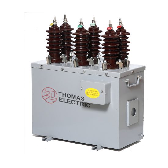
The VT-10K is a single-phase, indoor/outdoor-rated cast-resin insulated voltage transformer engineered for precise voltage transformation in 11kV (IEC) / 10kV (domestic) medium-voltage networks. Designed per IEC 61869-3 and GB/T 20840.3, it steps down system voltages to standardized secondary levels—typically 100 V or 110 V—for use with protective relays, revenue-grade meters, and SCADA interfaces. Its robust construction ensures long-term stability under continuous operation while maintaining tight accuracy tolerances across varying load and temperature conditions.
Operating Principle of Cast-Resin Insulation
Cast-resin insulation in the VT-10K employs vacuum pressure impregnation (VPI) of high-purity epoxy resin around the primary and secondary windings, followed by controlled thermal curing. This process eliminates air voids and moisture ingress pathways, resulting in a homogeneous dielectric structure with superior partial discharge resistance (<5 pC at 1.2 × Ur). The resin matrix provides mechanical support to the windings, suppresses corona formation, and offers excellent tracking resistance (CTI > 600 V). Unlike oil-filled units, cast-resin VTs require no maintenance of insulating fluid, eliminate fire hazards, and are suitable for confined or environmentally sensitive installations such as urban substations and indoor switchgear rooms.
Advantages Over Oil-Immersed Designs
Compared to traditional oil-immersed voltage transformers, the VT-10K’s dry-type cast-resin design eliminates risks associated with oil leakage, flammability, and environmental contamination. It features a lower profile and reduced weight (typically 35–45 kg), simplifying handling and mounting on bus supports or switchgear panels. Thermal performance is enhanced through direct heat conduction from windings to the resin body, enabling stable operation at ambient temperatures from –25°C to +40°C. Additionally, the absence of oil conservators or breathers reduces lifecycle costs and eliminates periodic oil sampling requirements. For applications requiring compliance with fire safety codes (e.g., IEC 60695), the VT-10K meets non-flammability class F1 per IEC 60754-2.
Typical Application Overview
The VT-10K is deployed in utility distribution substations, industrial power plants, commercial complexes, and renewable energy interconnection points where accurate voltage measurement and reliable fault detection are critical. It supports both metering (accuracy classes 0.2 or 0.5) and protection (3P or 6P) functions within a single unit, often configured with dual secondary windings. Common system configurations include grounded-wye, ungrounded delta, or open-delta arrangements for ground-fault detection. Its compact footprint allows integration into ring main units (RMUs), pad-mounted switchgear, and prefabricated substations without compromising safety clearances or thermal management.
Technical Specifications
The VT-10K adheres to stringent electrical and mechanical parameters defined by IEC 61869-3 and GB/T 20840.3. Key specifications ensure compatibility with global grid standards while supporting localized operational requirements.
Rated Electrical Parameters
Primary rated voltage: 11 kV (IEC standard); system voltage equivalent: 10 kV (domestic Chinese networks). Standard voltage ratios include 11,000/√3 : 100/√3 V (for wye-connected systems) and 11,000 : 100 V (line-to-line). Secondary outputs are available in 100 V or 110 V variants. Accuracy classes comply with IEC 61869-3: Class 0.2 (±0.2% ratio error, ±10′ phase displacement) for metering; Class 3P (±3% error up to 5× rated voltage) for protection during overvoltage transients. Rated burden ranges from 10 VA to 100 VA per winding, with thermal short-time withstand capability of 1 s at 100× rated voltage. Insulation level: LI 75 kV / AC 42 kV (1 min), per IEC 60071-1.
Construction and Core Materials
The magnetic core utilizes grain-oriented electrical steel (GOES) with low hysteresis loss (≤1.0 W/kg at 1.7 T, 50 Hz), ensuring minimal no-load losses (<15 W typical). Windings are made of oxygen-free copper (OFC) with Class F (155°C) thermal rating. The entire assembly is encapsulated in cycloaliphatic epoxy resin via VPI, providing IP00 protection (suitable for enclosed switchgear) or optional IP23 for outdoor pole-top mounting. Terminal blocks conform to IEC 61984, featuring screw-type connectors rated for 25 mm² Al/Cu conductors. Polarity is marked per IEC 61869-1: reducing polarity with “*” symbol on primary and secondary terminals.
Standard Service Conditions
Designed for continuous operation under: ambient temperature –25°C to +40°C; relative humidity ≤95% (non-condensing); altitude ≤1,000 m (derating required above 1,000 m per IEC 60071-2: –1% per 100 m for AC withstand voltage). Pollution degree: III (medium conductivity dust, temporary condensation). Installation orientation: vertical only, with primary terminal upward. Maximum operating frequency deviation: ±0.5 Hz from nominal 50/60 Hz. Short-circuit current withstand: not applicable (VTs are inherently current-limited by high impedance), but must be protected by upstream fuses rated ≤0.5 A (time-delay type).
Typical Applications
The VT-10K serves diverse roles across modern power infrastructure, leveraging its dual-function capability and environmental resilience.
Substation Secondary Metering
In 10/11kV distribution substations, the VT-10K provides voltage input to revenue-class kWh meters and power quality analyzers. With Class 0.2 accuracy, it ensures billing precision within ±0.2% over 80–120% of rated voltage and 25–100% of rated burden. Dual secondaries allow one winding to feed the utility meter while the other supplies local SCADA RTUs. In China, this configuration aligns with DL/T 614 requirements for smart grid data acquisition. Proper grounding of the secondary neutral is mandatory to prevent floating potentials; residual voltage windings (if present) enable zero-sequence monitoring for ground-fault detection in compensated networks.
Industrial Power Distribution Systems
Within manufacturing facilities, the VT-10K integrates into motor control centers (MCCs) and plant substations to supply voltage signals to multifunction relays (e.g., over/under-voltage, directional earth-fault). Its 3P-class protection winding maintains accuracy during transient overvoltages caused by switching surges or lightning, ensuring relay coordination per IEC 60255. In arc furnace or welding environments with high harmonic distortion, the GOES core minimizes saturation effects up to 13th harmonic. The cast-resin body resists chemical exposure from coolants or solvents, making it suitable for harsh industrial settings where oil-filled units pose contamination risks.
Renewable Energy Integration
Solar PV and wind farms utilize the VT-10K at the point of interconnection (POI) to monitor grid voltage for anti-islanding protection and reactive power control. During grid faults, the VT must accurately reflect depressed voltages to trigger ride-through protocols per GB/T 19964 or IEC 61400-21. The VT-10K’s fast response time (<20 ms) and low phase displacement error ensure synchronization accuracy for inverters. In microgrids operating in islanded mode, its stability under variable frequency (47–52 Hz) supports voltage regulation algorithms. Outdoor-rated versions with UV-stabilized resin housings withstand desert or coastal climates.
Rural and Suburban Distribution Networks
For rural electrification projects, the VT-10K is mounted on pole-top reclosers or sectionalizers to enable remote voltage monitoring via cellular RTUs. Its maintenance-free design reduces operational costs in areas with limited technical personnel. In suburban ring-main networks, it supports differential protection schemes when paired with matching CTs. The 11kV primary rating accommodates future grid upgrades from 10kV to 11kV without hardware replacement. Compliance with GB/T 20840.3 ensures interoperability with Chinese-made protection relays commonly deployed in Asia-Pacific regions.
Compliance with International Standards
The VT-10K is certified to both international and national standards, ensuring global deployability and regulatory acceptance.
IEC 61869-3 Certification Details
IEC 61869-3 specifies performance, testing, and marking requirements for inductive voltage transformers. The VT-10K undergoes type tests including temperature rise (Δθ ≤ 60 K for windings), short-circuit withstand (simulated via overvoltage test), and accuracy verification across burden and voltage ranges. Routine tests per clause 10 include polarity check, turns ratio (±0.25% tolerance), and power-frequency withstand (42 kV rms, 1 min). Partial discharge measurements are conducted at 1.2 × Ur/√3 with acceptance limit of 10 pC. Markings include rated voltage factor (1.2 for continuous, 1.5 for 30 s), accuracy class, and vector group (e.g., YNyn).
Alignment with GB/T 20840.3
GB/T 20840.3 is the Chinese national adoption of IEC 61869-3 with minor modifications. Key differences include: domestic system voltage reference of 10 kV (vs. IEC’s 11 kV), slightly relaxed phase displacement limits for Class 0.5 (±30′ vs. IEC’s ±20′), and mandatory seismic qualification for zones with PGA ≥0.2g. The VT-10K is dual-marked to satisfy both standards, enabling export to Belt and Road Initiative countries while meeting State Grid Corporation of China procurement specs. Testing labs accredited by CNAS perform verification per GB/T 16927.1 for impulse voltage (LI 75 kV) and wet AC withstand (34 kV, 1 min).
Testing and Certification Requirements
Certification requires submission of type test reports from ISO/IEC 17025-accredited laboratories. Critical tests include: temperature rise (resistance method, ambient 40°C), accuracy at 20%, 50%, 100%, and 120% of rated voltage, and ferroresonance immunity (per IEC TR 61869-100). The VT-10K incorporates damping resistors or auxiliary windings to suppress ferroresonance during single-phase switching. Certificates issued by TÜV, SGS, or CEPREI confirm compliance.
On-Site Testing Procedures
Post-installation verification ensures the VT-10K performs within specification before energization.
Insulation Resistance Test
Measure insulation resistance between primary-to-secondary, primary-to-ground, and secondary-to-ground using a 2,500 V DC megohmmeter. Acceptance criteria: ≥1,000 MΩ at 20°C. Correct for temperature using R20 = Rt × 2(20–t)/10. Values below 500 MΩ indicate moisture ingress or resin cracking. Perform before and after AC withstand test to detect insulation degradation.
Turns Ratio Test
Apply 100–200 V AC to the primary and measure secondary voltage with a calibrated voltmeter (accuracy class 0.1). Calculate ratio error: [(Vp/Vs)measured – (Vp/Vs)rated] / (Vp/Vs)rated × 100%. Acceptable tolerance: ±0.25% for metering class, ±1.0% for protection class. Use a dedicated ratio bridge (e.g., Omicron CT Analyzer) for automated testing.
Polarity Verification
Confirm reducing polarity using the DC kick test: connect a 6–12 V battery momentarily between primary terminals (* to +). Observe secondary voltage deflection on an analog voltmeter; positive kick at * terminal confirms correct polarity. Incorrect polarity causes 180° phase reversal, leading to false tripping in directional relays. Digital multimeters with min/max capture can also be used.
Power Frequency Withstand Voltage Test
Apply 42 kV rms (50 Hz) between primary and connected secondaries/ground for 1 minute. Leakage current must remain <3 mA. Gradually ramp voltage at 1 kV/s to avoid transient overstress. If breakdown occurs, inspect for surface tracking or internal voids. This test validates insulation integrity after transportation-induced mechanical stress.
Open-Circuit Characteristic Test
With secondary open, apply 0–120% of rated primary voltage and record excitation current. Plot V vs. I curve; knee point should exceed 1.5 × rated voltage. Excessive magnetizing current (>5% of rated secondary current at 100 V) indicates core saturation or shorted turns. This test is critical for ferroresonance assessment in ungrounded systems.
Preventive Maintenance Guide
Although cast-resin VTs are maintenance-free, periodic checks extend service life and prevent unexpected failures.
Annual Visual and Electrical Inspection
Inspect for surface cracks, UV degradation (outdoor units), terminal corrosion, or tracking marks. Clean with isopropyl alcohol if contaminated. Verify torque on terminal screws (8–10 N·m). Re-measure insulation resistance and compare to baseline; a 50% drop warrants further investigation. Check secondary wiring for loose connections that could cause arcing or measurement drift.
Five-Year Comprehensive Assessment
Perform full suite of on-site tests (ratio, polarity, insulation resistance, open-circuit curve). Compare results to commissioning data; significant deviations (>0.5% ratio shift) may indicate winding deformation or core damage. Thermographic scan under load can reveal hot spots at terminals. Replace if partial discharge exceeds 20 pC during offline testing.
Maintenance Intervals and Fault Diagnosis
| Interval | Action | Fault Indicators |
|---|---|---|
| Annually | Visual inspection, IR test | Cracks, discoloration, IR <500 MΩ |
| Every 5 years | Full electrical tests | Ratio error >0.5%, elevated excitation current |
| After fault event | Withstand test, PD measurement | Relay misoperation, blown fuses |
Common failure modes include secondary winding open-circuit (causing dangerous overvoltage) and resin delamination due to thermal cycling. Always de-energize and ground before inspection.
Conclusion
The VT-10K 11kV cast-resin voltage transformer represents a technically mature solution for accurate metering and dependable protection in modern 10/11kV power systems. Its compliance with IEC 61869-3 and GB/T 20840.3 ensures interoperability across global markets, while the VPI epoxy resin encapsulation delivers superior dielectric strength, environmental resilience, and fire safety compared to legacy oil-filled designs. Engineered with GOES silicon steel cores and precision-wound copper coils, the VT-10K maintains tight accuracy tolerances (Class 0.2 for metering, 3P for protection) under varying load, temperature, and harmonic conditions. Field-proven reliability is supported by rigorous type testing—including partial discharge, temperature rise, and ferroresonance immunity—and simplified by straightforward on-site verification procedures. With a design life of 25–30 years under standard service conditions, the VT-10K minimizes total cost of ownership through zero fluid maintenance, compact installation footprint, and resistance to pollution and moisture. Whether deployed in urban substations, industrial plants, renewable energy sites, or rural distribution networks, the VT-10K provides the foundational voltage signal integrity required for grid stability, revenue assurance, and asset protection in increasingly complex power systems.