Article Content
Introduction
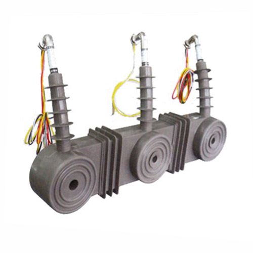
The CT-10KV current transformer is a critical component in medium-voltage electrical power systems, specifically engineered for applications operating at up to 10 kilovolts (kV). Designed to provide accurate current measurement and reliable protection functions, this instrument transformer isolates high-voltage primary circuits from low-voltage secondary instrumentation, thereby enhancing safety and enabling precise monitoring. Current transformers like the CT-10KV are indispensable in substations, industrial facilities, renewable energy installations, and utility distribution networks where dependable metering, control, and protective relaying are required.
Selecting the appropriate CT-10KV model demands careful consideration of multiple technical parameters to ensure compatibility with system requirements, regulatory standards (such as IEC 61869 or IEEE C57.13), and long-term operational reliability. An improperly specified current transformer can lead to inaccurate energy billing, failure to detect fault conditions, or even equipment damage due to insulation breakdown or thermal overload. This selection guide provides a structured approach to evaluating key specifications—starting with system voltage rating, followed by transformation ratio, accuracy class, burden requirements, and installation environment—to assist engineers and procurement specialists in making informed decisions.
System Voltage
The system voltage rating is a foundational parameter that determines the insulation capability and physical design of the CT-10KV. Although labeled “10kV,” this designation typically refers to the maximum system voltage for which the transformer is rated, not necessarily the nominal operating voltage. In practice, the CT-10KV is suitable for systems with nominal voltages ranging from 6.6 kV to 11 kV, depending on regional grid standards and grounding configurations.
It is essential to distinguish between phase-to-phase voltage (e.g., 10 kV) and phase-to-ground voltage (approximately 5.77 kV in a solidly grounded wye system). The CT’s insulation must withstand both continuous operating voltages and transient overvoltages caused by switching surges or lightning strikes. Therefore, the Basic Insulation Level (BIL) is a critical specification—commonly 75 kV or 95 kV for 10 kV class equipment—as defined by international standards.
Additionally, the system grounding method (solidly grounded, resistance grounded, or ungrounded) influences the voltage stress on the CT during ground-fault conditions. For instance, in an ungrounded system, a single line-to-ground fault can elevate the healthy phases to full phase-to-phase voltage relative to ground, requiring the CT to endure higher sustained voltages. Always verify that the CT-10KV model complies with the local utility’s voltage and insulation requirements before installation.
| Parameter | Typical Value for CT-10KV | Relevant Standard |
|---|---|---|
| Maximum System Voltage | 12 kV | IEC 60038 |
| Nominal System Voltage Range | 6.6 kV – 11 kV | Local Grid Codes |
| Basic Insulation Level (BIL) | 75 kV or 95 kV | IEC 60071-1 |
| Power Frequency Withstand Voltage | 28 kV (1 min) | IEC 61869-3 |
Transformation Ratio
The transformation ratio (also called turns ratio) defines the relationship between the primary current (IP) and the secondary current (IS) under normal operating conditions. For the CT-10KV, common ratios include 50/5, 100/5, 200/5, 400/5, 600/5, and 800/5 A, though custom ratios such as 100/1 or 150/5 may also be available. This ratio directly impacts the scaling of measured current values and must align with the input requirements of connected devices—such as protective relays, energy meters, or SCADA systems—which typically expect standardized secondary currents of 1 A or 5 A.
Selecting the correct ratio involves analyzing both normal load current and potential fault current levels. The primary current rating should exceed the maximum expected continuous load current (including future expansion) but remain low enough to ensure adequate secondary output during minimum load conditions for accurate metering. For example, if a feeder carries a peak load of 350 A, a 400/5 ratio would be appropriate, whereas a 600/5 ratio might result in poor resolution at light loads.
Furthermore, the CT must maintain performance during short-circuit events. The ratio accuracy under high overcurrent conditions is influenced by the core material and cross-sectional area. A CT with insufficient core size may saturate during faults, distorting the secondary waveform and causing protective relays to malfunction. Therefore, the rated symmetrical short-circuit factor (e.g., 10×, 20×, or 30× the primary rating) must be verified against the prospective fault current at the installation point.
Multiratio CTs offer flexibility by providing multiple tap points on the secondary winding (e.g., 400/5/5 A with taps at 200/5 and 400/5). These are useful in applications where load profiles may change over time or where different instruments require varying current ranges. However, unused taps must be shorted to prevent dangerous open-circuit conditions.
| Primary Current (A) | Secondary Current (A) | Common Applications | Notes |
|---|---|---|---|
| 50 | 5 | Small feeders, auxiliary circuits | Low burden; verify meter sensitivity |
| 200 | 5 | Medium industrial loads | Balanced accuracy and fault response |
| 400 | 5 | Main distribution feeders | Most common standard ratio |
| 800 | 5 | High-capacity circuits | Requires larger core; higher cost |
| 100 | 1 | Long cable runs, digital relays | Reduces burden; lower secondary current |
When specifying the transformation ratio, always coordinate with relay and meter manufacturers to confirm compatibility. Additionally, consider the impact of ratio selection on the CT’s accuracy class and thermal rating, as these are interdependent design factors.
Accuracy Class
The accuracy class of a CT-10KV quantifies its ability to reproduce the primary current faithfully in the secondary circuit within defined limits under specified operating conditions. Accuracy is expressed as a percentage error in current magnitude and phase angle, and it varies based on whether the CT is used for metering (revenue or monitoring) or protection purposes. Common accuracy classes include 0.2, 0.5, 1.0, 3, 5P10, 5P20, and 10P10, where “P” denotes protection class.
For metering applications, classes 0.2 and 0.5 are typical for revenue-grade billing, ensuring errors within ±0.2% and ±0.5%, respectively, at 100% to 120% of rated current. Class 1.0 is acceptable for general monitoring where high precision is not critical. These classes are defined under IEC 61869-2 and assume a specific standard burden (e.g., 2.5 VA, 5 VA, or 10 VA at 5 A secondary).
Protection-class CTs (e.g., 5P10) are designed to remain linear and deliver accurate current representation during high-magnitude fault conditions. The notation “5P10” means the composite error will not exceed 5% at 10 times the rated primary current. Similarly, “10P20” allows up to 10% error at 20× overcurrent. Selecting the appropriate protection class requires knowledge of the maximum fault current and the relay’s operating characteristics—especially for instantaneous or differential protection schemes that demand minimal saturation.
It is crucial to match the CT’s accuracy class with its connected burden. Exceeding the rated burden (due to long cables, multiple devices, or high-impedance relays) degrades accuracy and may push the CT into saturation prematurely. Always calculate the total loop impedance (including wiring resistance) and verify it falls within the CT’s specified burden limit for the chosen accuracy class.
| Accuracy Class | Application | Max Composite Error | Test Current | Typical Burden (VA) |
|---|---|---|---|---|
| 0.2 | Revenue metering | ±0.2% | 100%–120% In | 2.5 or 5 |
| 0.5 | Precision monitoring | ±0.5% | 100%–120% In | 5 |
| 1.0 | General indication | ±1.0% | 100%–120% In | 5 or 10 |
| 5P10 | Overcurrent protection | ≤5% | 10 × In | 15 or 30 |
| 10P20 | Backup protection | ≤10% | 20 × In | 15 or 30 |
5. Burden Calculation
The burden of a current transformer (CT) is the total impedance presented to its secondary winding, comprising connected devices (relays, meters, leads) and wiring. Accurate burden calculation ensures the CT operates within its accuracy class and avoids saturation during normal or fault conditions.
Burden is typically expressed in volt-amperes (VA) at a specified power factor or as an equivalent impedance in ohms. The total burden \( Z_b \) is calculated as:
\[ Z_b = Z_{\text{relay}} + Z_{\text{leads}} + Z_{\text{connections}} \]
Where:
- \( Z_{\text{relay}} \): Impedance of the connected protective relay or metering device.
- \( Z_{\text{leads}} \): Total impedance of the secondary wiring (round-trip distance × resistance per unit length).
- \( Z_{\text{connections}} \): Contact resistance at terminals and splices (often estimated at 0.01–0.05 Ω).
For example, with 200 ft of #12 AWG copper wire (resistance ≈ 1.6 Ω/1000 ft), round-trip lead resistance is:
\[ R_{\text{leads}} = 2 \times \frac{200}{1000} \times 1.6 = 0.64\ \Omega \]
If the relay burden is 0.2 Ω and connections add 0.03 Ω, total burden is 0.87 Ω. The corresponding VA burden at 5 A secondary current is:
\[ \text{VA} = I^2 \times Z = 5^2 \times 0.87 = 21.75\ \text{VA} \]
CTs must be rated for a standard burden (e.g., B-0.5, B-1.0) that exceeds the calculated value. Undersized burden ratings can cause ratio errors or waveform distortion, compromising protection coordination.
| Component | Typical Impedance (Ω) | Notes |
|---|---|---|
| Electromechanical Relay | 0.1 – 0.5 | Varies by model and setting |
| Numerical Relay | 0.02 – 0.1 | Low burden due to solid-state inputs |
| #12 AWG Copper Lead (per 100 ft round-trip) | 0.32 | Based on 1.6 Ω/1000 ft one-way |
| Terminal Connections | 0.01 – 0.05 | Depends on cleanliness and torque |
| Total Allowable Burden (B-1.0 CT) | 1.0 | Maximum at 5 A, 60 Hz |
Always verify burden using manufacturer data sheets and include a safety margin (typically 20%) to account for aging, temperature effects, and future modifications.
6. Short-Circuit Performance
Current transformers must withstand high-magnitude fault currents without mechanical damage or loss of accuracy. Short-circuit performance is evaluated based on thermal and dynamic (electrodynamic) withstand capabilities.
Thermal Withstand relates to the CT’s ability to handle I²t heating during a fault. The thermal short-time current rating (e.g., 40 kA for 1 second) must exceed the system’s prospective fault current multiplied by the duration of the fault-clearing time. Exceeding this rating can melt windings or degrade insulation.
Dynamic Withstand addresses mechanical forces between conductors during peak fault current. These forces are proportional to the square of the instantaneous current and can deform or displace windings if not properly braced. CTs are typically rated to withstand 2.5 times the RMS symmetrical short-circuit current as peak asymmetrical current.
Key considerations:
- Verify that the CT’s short-circuit rating matches or exceeds the bus fault level at its installation point.
- Account for X/R ratio; high X/R systems produce higher DC offset, increasing peak current.
- Ensure the CT knee-point voltage is sufficient to avoid saturation during external faults, which could compromise differential or distance protection.
Saturation during internal faults may be acceptable if the relay operates quickly, but saturation during external faults can cause false tripping. Use C-class CTs (e.g., C800) for high-impedance differential schemes where high excitation voltage is required.
| Parameter | Requirement | Verification Method |
|---|---|---|
| Thermal Rating | ≥ System Isc × √(tfault/1s) | Compare with utility short-circuit study |
| Dynamic Rating | ≥ 2.5 × Isc(rms) | Check CT nameplate or test report |
| Knee-Point Voltage (Vk) | Vk > If × (Rct + Rb) | Excitation test per IEEE C57.13 |
| Accuracy Class Under Fault | Maintain within limits per IEC 61869-2 | Transient response simulation |
Always coordinate CT short-circuit ratings with breaker interrupting capacity and relay operating time to ensure system integrity during faults.
7. Environmental Considerations
Environmental factors significantly influence CT selection, installation, and long-term reliability. Key parameters include ambient temperature, humidity, altitude, pollution, and exposure to chemicals or UV radiation.
Temperature: CTs are typically rated for operation between –25°C and +55°C. Extreme cold can embrittle insulation, while high temperatures accelerate insulation aging and increase copper losses. Derating may be required above 40°C ambient.
Altitude: Above 1000 meters (3300 ft), air density decreases, reducing dielectric strength and cooling efficiency. CTs installed above this altitude often require derating (e.g., 1% per 100 m) or special design with increased creepage distance.
Pollution and Moisture: In coastal, industrial, or high-humidity areas, condensation and salt/fume deposits can cause surface tracking. Outdoor CTs should have a minimum IP54 rating, with IP65 recommended for harsh environments. Use silicone rubber or EPDM housings for superior hydrophobicity.
UV and Chemical Exposure: Prolonged sunlight degrades certain polymers. Specify UV-stabilized materials for outdoor use. In chemical plants, verify housing compatibility with local contaminants (e.g., chlorine, sulfur compounds).
| Environment | Recommended CT Features | Standards Reference |
|---|---|---|
| Coastal / High Humidity | Stainless steel hardware, hydrophobic housing, conformal coating on terminals | IEC 60068-2-11 (salt mist) |
| Industrial (Chemical) | Chemical-resistant epoxy resin, sealed terminal chamber | IEC 60721-3-3 (Class 3C2) |
| High Altitude (>2000 m) | Increased creepage, derated thermal capacity | IEC 60076-2 |
| Outdoor (General) | UV-resistant polymer, IP65 rating, drainage vents | IEC 60529 (IP code) |
Always consult site-specific environmental data during specification. Field failures due to environmental stress are preventable with proper material selection and enclosure design.
8. CT Selection and Installation Checklist
Use this checklist to ensure comprehensive evaluation and correct deployment of current transformers in protection and metering applications.
| # | Check Item | Status (✓/✗/N/A) | Notes |
|---|---|---|---|
| 1 | Primary current rating matches max load + 20% margin | ||
| 2 | Secondary current standard (1 A or 5 A) aligns with relay input | ||
| 3 | Accuracy class verified for application (e.g., 5P20 for protection) | ||
| 4 | Total burden ≤ CT rated burden (with 20% safety margin) | ||
| 5 | Short-circuit current rating ≥ system fault level | ||
| 6 | Knee-point voltage sufficient to avoid saturation during external faults | ||
| 7 | Environmental rating suitable for location (IP, temp, altitude) | ||
| 8 | Correct polarity marking observed during installation | ||
| 9 | Secondary circuit grounded at single point (per IEEE C57.13) | ||
| 10 | Open-circuit protection (shorting switch or automatic shorting device) installed |
Complete this checklist during design review and again during commissioning. Document all verifications for audit and maintenance records. Never energize a CT with an open secondary—this can generate lethal voltages and permanently damage the core.