Article Content
Outdoor/Indoor 11kV Cast-Resin Current Transformer LAJ-10Q – IEC 61869-2 Compliant
Introduction to the LAJ-10Q Current Transformer
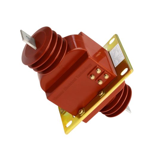
The LAJ-10Q is a medium-voltage cast-resin current transformer (CT) engineered for precise current measurement and dependable protective relaying in 11kV (IEC-rated) or 10kV (domestic system) electrical networks. Designed for both indoor switchgear and outdoor substation environments, this device leverages advanced vacuum pressure impregnation (VPI) epoxy resin technology to deliver superior dielectric strength, mechanical robustness, and long-term thermal stability. Unlike traditional oil-immersed CTs, the LAJ-10Q eliminates fire hazards, environmental leakage risks, and maintenance-intensive fluid management, making it ideal for urban substations, industrial facilities, and renewable energy interconnection points.
Operating Principle of Cast-Resin Insulation
Cast-resin insulation in the LAJ-10Q utilizes a high-purity cycloaliphatic epoxy resin system processed under vacuum and pressure to fully impregnate the primary conductor, secondary windings, and magnetic core assembly. This VPI technique ensures complete void elimination, preventing partial discharge inception even under continuous overvoltage stress. The cured resin forms a monolithic, hydrophobic structure with a relative permittivity (εr) of approximately 4.2 and volume resistivity exceeding 1×10¹⁴ Ω·cm at 20°C. Thermal class F (155°C) insulation allows sustained operation at ambient temperatures up to 40°C with a 10K hotspot temperature rise margin. The resin’s coefficient of thermal expansion closely matches that of copper and silicon steel, minimizing mechanical stress during thermal cycling—a critical factor for 25+ year service life in cyclic load environments.
Advantages Over Oil-Immersed Designs
Compared to oil-filled CTs, the LAJ-10Q offers significant operational and safety benefits. Its solid insulation eliminates flammability risks (meeting IEC 60695 glow-wire ignition test requirements), removes the need for oil sampling or level monitoring, and prevents PCB contamination concerns. The compact, lightweight design (typically 12–15 kg) simplifies handling and reduces structural support requirements. Additionally, cast-resin CTs exhibit lower dielectric losses (tan δ < 0.005 at 50 Hz) and superior resistance to moisture ingress—critical for coastal or high-humidity installations where condensation can compromise oil-paper insulation systems. The absence of breathing mechanisms also prevents internal contamination from dust, salt, or chemical vapors.
Typical Application Overview
The LAJ-10Q serves dual roles: precision metering (accuracy classes 0.2S, 0.5S) and protective relaying (classes 5P10, 5P20). It is commonly deployed on 10kV ring main units (RMUs), pad-mounted transformers, and feeder breakers in distribution substations. In industrial settings, it monitors motor feeders, capacitor banks, and arc furnace circuits. For renewable integration, it provides grid-compliant current signals for solar inverter synchronization and fault ride-through compliance. Secondary outputs are standardized to 1A or 5A, interfacing directly with digital meters, protective relays (e.g., SEL-751, Siemens 7SJ62), and SCADA RTUs without intermediate transducers.
Technical Specifications
The LAJ-10Q adheres to stringent electrical and environmental parameters defined by IEC 61869-2 and GB/T 20840.2, ensuring interoperability across global power systems.
| Parameter | Value |
|---|---|
| Rated System Voltage (Um) | 11 kV (IEC) / 10 kV (Domestic) |
| Insulation Level (LI/AC) | 75 kV / 28 kV (1 min) |
| Primary Current (Ip) | 50–3000 A (standard ratios) |
| Secondary Current (Is) | 1 A or 5 A |
| Metering Accuracy Class | 0.2S, 0.5S (per IEC 61869-2) |
| Protection Accuracy Class | 5P10, 5P20 |
| Rated Output (Burden) | 2.5–30 VA (at rated current) |
| Short-Time Thermal Current | 20×In for 1 s (e.g., 60 kA for 3000 A CT) |
| Dynamic Withstand Current | 50×In peak (e.g., 150 kA for 3000 A CT) |
| Ambient Temperature Range | −25°C to +40°C |
| Altitude Limit | ≤1000 m (derating required above) |
| Relative Humidity | ≤95% (non-condensing) |
Core and Winding Construction
The magnetic circuit employs grain-oriented electrical steel (GOES) with a maximum specific loss of 1.0 W/kg at 1.7 T and 50 Hz. Core lamination thickness is 0.3 mm, annealed to minimize hysteresis losses. Secondary windings use enameled copper wire (Class 180°C insulation) wound with tight pitch control to reduce leakage reactance. Multiple secondary windings (up to three) can be provided—one for metering (0.2S), one for protection (5P20), and a third for differential schemes. Terminal blocks comply with IEC 60947-7-1, featuring screw-type connectors rated for 6 mm² conductors with IP2X finger-safe covers.
Environmental and Mechanical Ratings
Housed in a UV-stabilized cycloaliphatic resin casing, the LAJ-10Q achieves IP54 protection per IEC 60529 when mounted vertically. The creepage distance exceeds 240 mm (22 mm/kV for 11 kV), satisfying pollution degree 3 requirements. Mounting options include M12 threaded studs or DIN rail brackets. The transformer withstands seismic loads up to 0.5g horizontal acceleration (IEC 60068-2-57), suitable for earthquake-prone regions. Weight varies by ratio: 12 kg (100/5 A) to 15 kg (3000/5 A).
Typical Applications
The LAJ-10Q’s versatility enables deployment across diverse power infrastructure segments.
Substation Secondary Metering
In 11kV/0.4kV distribution substations, the LAJ-10Q provides revenue-grade current inputs to AMI meters and tariff analyzers. Installed on outgoing feeders, its 0.2S accuracy ensures billing precision even at 1% of rated current (per IEC 62053-22). For example, a 400/5 A unit maintains ±0.2% error from 4 A to 400 A primary current. The low phase displacement (<±10 minutes at 100% In) supports vector group verification in three-phase systems. Integration with IEC 61850-9-2 LE process buses is facilitated via compatible merging units.
Industrial Power Distribution
Within manufacturing plants, the LAJ-10Q monitors critical loads such as induction motors (≥100 kW), rectifier transformers, and harmonic-generating equipment. Its 5P20 protection winding reliably drives overcurrent relays during bolted faults while resisting saturation from DC offset (X/R ≤ 15). In steel mills, units with reinforced cores handle asymmetrical short-circuit currents without remanence-induced errors. Secondary terminals are often routed to local PLCs for real-time load profiling and predictive maintenance analytics.
Renewable Energy Integration
Solar PV and wind farms utilize the LAJ-10Q at the point of common coupling (PCC) to meet grid code requirements (e.g., IEEE 1547, ENTSO-E). During low-voltage ride-through (LVRT) events, the CT must accurately reproduce fault currents with harmonics up to the 13th order. The LAJ-10Q’s linear B-H curve up to 2.0 T ensures fidelity under distorted waveforms. For anti-islanding detection, its 0.5S winding feeds frequency relays with minimal phase shift (<±5 minutes).
Rural and Suburban Distribution Networks
In overhead line sections, pole-mounted LAJ-10Q units (with weatherproof terminal boxes) enable remote fault location and load balancing. Their immunity to bird ingress and vandalism makes them preferable over open-core designs. In smart grid pilots, they interface with distribution automation terminals (DATs) for self-healing network operations. The 1A secondary option reduces copper losses over long cable runs (>100 m) to control houses.
Compliance with International Standards
The LAJ-10Q is certified to IEC 61869-2:2012 (Instrument transformers – Part 2: Additional requirements for current transformers) and aligns with China’s GB/T 20840.2-2014.
IEC 61869-2 Certification Requirements
Compliance mandates rigorous testing per Clause 7 of IEC 61869-2. Key verifications include: accuracy limit factor (ALF) validation at 100% and 120% of rated burden; temperature rise tests (Δθ ≤ 60 K for windings); and impulse withstand (75 kV, 1.2/50 μs). The standard requires composite error ≤5% for 5P class at ALF×In. Partial discharge levels must remain below 10 pC at 1.2×Um/√3. Type tests are conducted by accredited labs (e.g., KEMA, CESI), with routine tests performed on every unit.
Alignment with GB/T 20840.2
GB/T 20840.2 adopts IEC 61869-2 with minor national deviations. Notably, Chinese standards specify a higher short-time thermal current (25×In for 1 s vs. IEC’s 20×In) and require additional salt fog testing (1000 hours per GB/T 2423.17) for coastal deployments. The LAJ-10Q meets both by incorporating thicker resin walls and enhanced corona shielding. Domestic certification (CQC mark) includes factory audits per CNAS-CL01.
Key Differences Between IEC and Domestic Standards
While IEC emphasizes functional performance, GB standards prioritize environmental resilience. For instance, GB/T 20840.2 mandates −40°C cold-start testing (vs. IEC’s −25°C) and specifies stricter vibration limits (5–500 Hz sweep, 0.7g RMS). The LAJ-10Q’s design accommodates these through low-temperature-toughened resin formulations and constrained-layer damping mounts. Both standards converge on core material requirements (GOES with B8 ≥ 1.88 T), ensuring magnetic consistency.
On-Site Testing Procedures
Post-installation verification ensures the LAJ-10Q performs within specified tolerances.
Insulation Resistance Test
Using a 2500 V DC megohmmeter, measure insulation resistance between primary-to-secondary, primary-to-ground, and secondary-to-ground. Acceptance criteria: ≥1000 MΩ at 20°C. Correct for temperature using RT = R20 × 2(20−T)/10. Values below 500 MΩ indicate moisture ingress or resin cracking. Perform before and after power frequency withstand tests to detect degradation.
Turns Ratio Test
Apply 1–5 V AC (50 Hz) to the secondary winding and measure induced primary voltage. Calculate ratio as Vs/Vp. Tolerance: ±0.25% for metering classes, ±1% for protection. Alternatively, use a dedicated CT analyzer (e.g., Omicron CT Analyzer) injecting 1–10 A into the primary. Verify all taps if multi-ratio.
Polarity Test
Confirm reducing polarity per IEC 61869-2 Figure 3. Apply a 3–6 V DC pulse to P1–P2; observe momentary positive deflection on a center-zero galvanometer connected to S1–S2. Incorrect polarity causes relay misoperation—especially in differential schemes. Document results with timestamped oscillograms.
Power Frequency Withstand Voltage Test
Apply 28 kV RMS (50 Hz) for 60 seconds between primary and grounded secondary/core. Use a calibrated test transformer with overcurrent trip (≤100 mA). No flashover or disruptive discharge permitted. Ramp voltage at 1 kV/s. Pre-test: verify grounding continuity (<0.1 Ω).
Short-Circuit Test for CT Saturation Verification
Inject 20×In (e.g., 200 A for 10 A primary) into the primary with secondary shorted. Monitor secondary current waveform via oscilloscope. Saturation onset should occur beyond 20×In for 5P20 class. Composite error must remain ≤5%. This validates ALF under fault conditions.
Preventive Maintenance Guide
Proactive maintenance extends service life and prevents unexpected failures.
Periodic Inspection Protocol
Annual visual checks include: resin surface integrity (no cracks, tracking, or UV degradation); terminal tightness (torque: 2.5 N·m for M4 screws); and grounding continuity (<0.5 Ω). Clean housings with isopropyl alcohol; avoid abrasive cleaners. In polluted areas, inspect creepage distance for salt/dust accumulation—flush with deionized water if conductivity >20 μS/cm.
Maintenance Intervals and Fault Diagnosis
Every five years, perform full electrical tests (Sections 5.1–5.5). Common faults: open secondary circuits (causing core saturation and overheating), moisture-induced partial discharge (audible buzzing), and terminal corrosion (increased contact resistance). If ratio error exceeds tolerance, check for shorted secondary turns via excitation curve comparison. Replace units showing tan δ >0.01 at 10 kV.
| Interval | Activities |
|---|---|
| Annual | Visual inspection, IR thermography, grounding check |
| 5 Years | Full electrical tests, excitation curve analysis |
| 10 Years | Partial discharge mapping (if available), core remanence check |
Conclusion
The LAJ-10Q 11kV cast-resin current transformer represents a benchmark in medium-voltage instrumentation, combining IEC 61869-2-certified accuracy with rugged environmental resilience. Its VPI epoxy resin construction eliminates the operational liabilities of oil-filled alternatives while delivering metrological precision down to 1% of rated current—essential for modern smart grids and revenue metering. Engineered with GOES cores and optimized magnetic circuits, it maintains linearity under high fault currents (5P20 class) and distorted waveforms typical of industrial and renewable applications. Compliance with both international (IEC) and domestic (GB) standards ensures seamless integration across global markets, from urban substations to remote rural feeders. With a design life of 25–30 years under standard service conditions (−25°C to +40°C, ≤1000 m altitude), the LAJ-10Q minimizes lifecycle costs through zero-fluid maintenance and exceptional reliability. Its compact form factor and dual indoor/outdoor rating further enhance deployment flexibility, making it a preferred choice for utilities and industrial operators prioritizing safety, accuracy, and long-term asset integrity.
Frequently Asked Questions (FAQ)
Q1: Can the LAJ-10Q be used on a 10kV system even though it’s rated 11kV?
Yes. The 11kV rating per IEC 60038 corresponds to the maximum system voltage (Um) for a nominal 10kV network. The LAJ-10Q is fully compatible with 10kV domestic systems and meets all insulation requirements for this application.
Q2: What happens if the secondary circuit is left open during operation?
An open secondary circuit induces dangerously high voltages (several kV) across the terminals due to core saturation, risking insulation failure and personnel hazard. Always ensure the secondary is shorted or connected to a burden before energizing the primary. The LAJ-10Q includes warning labels per IEC 61869-2 Clause 6.103.
Q3: Is the LAJ-10Q suitable for high-altitude installations (>1000 m)?
Derating is required above 1000 m. For every 100 m above 1000 m, reduce the rated voltage by 1.25% or apply a correction factor per IEC 60071-2. Consult the manufacturer for customized designs with extended creepage or pressurized enclosures.
Q4: Can multiple secondary windings share a common core?
Yes. The LAJ-10Q can be ordered with up to three independent secondary windings (e.g., 0.2S for metering, 5P20 for overcurrent, and 5P20 for earth fault) on a single core. Each winding is electrically isolated and tested separately per IEC 61869-2 Annex B.
Q5: What is the minimum bending radius for secondary leads?
Secondary cables exiting the terminal box must maintain a bending radius ≥6× cable diameter to prevent conductor fatigue. For standard 2.5 mm² PVC-insulated leads, this equals 15 mm. Avoid sharp edges near mounting brackets.