Article Content
Introduction
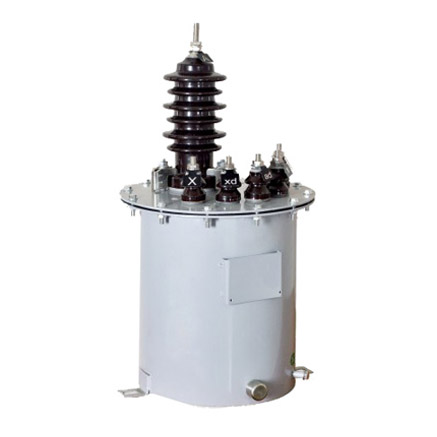
The LB-10W Current Transformer (CT) is a critical component in medium-voltage power systems, specifically engineered for reliable and accurate current measurement and protection applications at system voltages up to 10 kV. Designed with robust insulation and high thermal stability, the LB-10W ensures safe operation under demanding electrical conditions while maintaining precise performance over extended service life. This selection guide provides essential technical information to assist engineers, system designers, and procurement specialists in correctly specifying and deploying the LB-10W CT within their 10 kV infrastructure.
Current transformers like the LB-10W serve two primary functions: they step down high primary currents to standardized, manageable secondary levels (typically 1 A or 5 A) for use by metering instruments, relays, and monitoring devices; and they electrically isolate these sensitive downstream components from the high-voltage primary circuit, thereby enhancing personnel and equipment safety. The “LB” designation typically denotes a resin-cast, indoor-type bushing current transformer, while the “10W” suffix indicates suitability for 10 kV class systems with specific short-time thermal and dynamic withstand capabilities.
Selecting the appropriate CT involves careful consideration of multiple interrelated parameters—system voltage, transformation ratio, accuracy class, burden rating, and environmental conditions. Misapplication can lead to inaccurate metering, nuisance tripping of protective relays, or even catastrophic failure under fault conditions. This guide focuses on the first half of the selection process, covering foundational criteria that directly influence compatibility and performance within a 10 kV network.
System Voltage
The LB-10W current transformer is rated for use in three-phase alternating current (AC) systems with a nominal system voltage of 10 kV. However, correct application requires understanding the distinction between nominal voltage, maximum system voltage, and insulation coordination requirements. The “10 kV” rating refers to the highest RMS voltage of the system for which the CT is designed, in accordance with international standards such as IEC 61869-3 and GB/T 20840.
In practice, a 10 kV system may operate at voltages ranging from 6 kV to 12 kV depending on regional grid standards and load conditions. The LB-10W is typically tested and certified for a maximum system voltage (Um) of 12 kV, ensuring adequate insulation margin during transient overvoltages. Its power frequency withstand voltage is usually 42 kV (RMS, 1-minute), and its lightning impulse withstand voltage is 75 kV (peak), providing robust protection against switching surges and atmospheric disturbances.
It is imperative that the CT’s rated voltage matches or exceeds the maximum operating voltage of the installation point. Installing an LB-10W in a system exceeding 12 kV Um compromises dielectric integrity and violates safety codes. Conversely, using it in lower-voltage systems (e.g., 6.6 kV or 3.3 kV) is permissible but may not be cost-optimal unless standardization across multiple voltage levels is desired.
The table below summarizes key voltage-related ratings for the LB-10W:
| Parameter | Symbol | Value | Standard Reference |
|---|---|---|---|
| Nominal System Voltage | Un | 10 kV | IEC 60038 |
| Maximum System Voltage | Um | 12 kV | IEC 61869-3 |
| Power Frequency Withstand Voltage (1 min) | Up | 42 kV RMS | IEC 60060-1 |
| Lightning Impulse Withstand Voltage | Uimp | 75 kV peak | IEC 60060-1 |
Note that the LB-10W is intended for indoor installations only. Outdoor use requires additional weatherproofing or alternative CT designs with UV-resistant and hydrophobic housing.
Transformation Ratio
The transformation ratio (also called turns ratio or current ratio) defines the relationship between the primary current (Ip) flowing through the power conductor and the standardized secondary current (Is) delivered to connected devices. For the LB-10W, common ratios include 50/5, 100/5, 200/5, 400/5, 600/5, 800/5, and 1000/5 A, though custom ratios such as 100/1 or 400/1 A are also available upon request. The ratio is expressed as Ip:Is, where the secondary is typically normalized to 1 A or 5 A per international convention.
Selecting the correct ratio is crucial for both measurement accuracy and protection reliability. The primary current rating should be equal to or slightly higher than the normal full-load current of the circuit. If the ratio is too high (e.g., selecting 1000/5 for a 100 A load), the secondary current becomes too small relative to the instrument’s minimum resolution, leading to poor metering accuracy at light loads. Conversely, if the ratio is too low (e.g., 50/5 for a 600 A feeder), the CT may saturate during normal operation or fault conditions, distorting the secondary waveform and causing protective relays to malfunction.
For protection applications, the CT must maintain acceptable accuracy well beyond the nominal current—often up to 10× or 20× rated current during fault conditions. This is governed by the accuracy limit factor (ALF), discussed in the Accuracy Class section. For metering, the focus is on precision at 5% to 120% of rated current.
Multi-ratio CTs offer flexibility by providing multiple secondary taps (e.g., 400–600–800/5 A on a single unit). These are achieved through intermediate tap points on the secondary winding. When using tapped ratios, only the selected tap and the common terminal should be connected; unused taps must remain open and insulated to prevent short circuits.
The following table lists standard transformation ratios for the LB-10W and their typical applications:
| Transformation Ratio (Ip/Is) | Typical Primary Load Range (A) | Common Applications | Secondary Current at Full Load |
|---|---|---|---|
| 50/5 | 30 – 60 | Small transformers, lighting panels | 5 A |
| 100/5 | 60 – 120 | Distribution feeders, motor control centers | 5 A |
| 200/5 | 120 – 240 | Medium industrial loads | 5 A |
| 400/5 | 240 – 480 | Main incomers, large motors | 5 A |
| 600/5 | 360 – 720 | Substation feeders | 5 A |
| 800/5 | 480 – 960 | Heavy industrial distribution | 5 A |
| 1000/5 | 600 – 1200 | High-capacity switchgear | 5 A |
| 400/1 | 240 – 480 | Long-distance metering (reduced burden) | 1 A |
When choosing between 1 A and 5 A secondary currents, consider the total burden (impedance) of connected devices and wiring. A 1 A system reduces power loss over long cable runs but requires more sensitive (and often more expensive) instruments. Most legacy systems in Asia and Europe use 5 A, while newer installations increasingly adopt 1 A for efficiency.
Accuracy Class
Accuracy class defines the permissible error in current transformation under specified operating conditions. For the LB-10W current transformer, accuracy classes are designated according to IEC 61869-2 and include both metering classes (e.g., 0.2, 0.5, 1) and protection classes (e.g., 5P10, 10P20). Each class specifies the maximum composite error (expressed as a percentage) at a given fraction of the rated current or at a multiple of rated current for protection applications.
Metering accuracy classes apply to steady-state conditions within the normal operating range (typically 5% to 120% of rated primary current). For example, a CT rated 0.5 class must not exceed ±0.5% current error and ±18 minutes phase displacement at 100% rated current and at the specified burden. Higher precision classes (0.2, 0.2S, 0.5S) are used for revenue metering, while general-purpose monitoring may use class 1 or 3.
Protection accuracy classes (denoted with “P”) ensure the CT remains sufficiently linear during high-current fault conditions. The designation “5P10” means the composite error must not exceed 5% at 10 times the rated primary current, under the rated burden. Similarly, “10P20” allows up to 10% error at 20× rated current. The number after “P” is the Accuracy Limit Factor (ALF), indicating how far into the fault current range the CT maintains usable output.
It is critical to match the accuracy class to the application:
- Class 0.2 / 0.2S: High-accuracy revenue metering (utility billing)
- Class 0.5 / 0.5S: Sub-metering, energy management
- Class 1: General indication, non-critical monitoring
- 5P10 / 5P20: Overcurrent, earth-fault protection requiring moderate accuracy
- 10P10 / 10P20: Basic protection where saturation margin is prioritized over precision
The LB-10W is commonly available in dual-winding configurations—one core for metering (e.g., 0.5 class) and another for protection (e.g., 10P20)—to satisfy both functional requirements within a single unit. The rated burden (in VA) must also be considered; accuracy is only guaranteed when the total connected burden (wiring + device impedance) does not exceed the CT’s rated burden (e.g., 15 VA, 30 VA).
Below is a comparison of common accuracy classes for the LB-10W:
| Accuracy Class | Type | Max Current Error | Test Condition | Typical Burden (VA) |
|---|---|---|---|---|
| 0.2 | Metering | ±0.2% | 100% In, cosφ = 0.8 | 10–30 |
| 0.5 | Metering | ±0.5% | 100% In, cosφ = 0.8 | 10–30 |
| 1 | Metering | ±1.0% | 100% In, cosφ = 0.8 | 5–15 |
| 5P10 | Protection | ≤5% composite error | 10 × In, rated burden | 15–30 |
| 10P20 | Protection | ≤10% composite error | 20 × In, rated burden | 15–30 |
Note that accuracy degrades if the actual burden exceeds the rated value or if the CT operates outside its specified current range. Always verify the total loop impedance during design to ensure compliance with the selected accuracy class.
5. Burden Calculation
The burden of a current transformer (CT) is the total impedance presented to its secondary winding, comprising connected devices (relays, meters, transducers) and interconnecting wiring. Accurate burden calculation is essential to ensure CT accuracy class compliance and prevent saturation under normal or fault conditions.
Burden is typically expressed in volt-amperes (VA) at a specified secondary current (usually 1 A or 5 A). The total burden \( Z_b \) is calculated as:
\[
Z_b = Z_{\text{lead}} + Z_{\text{device}}
\]
Where:
- \( Z_{\text{lead}} \) = Impedance of the connecting leads
- \( Z_{\text{device}} \) = Impedance of connected instruments
Lead impedance depends on conductor length, cross-sectional area, and resistivity. For copper conductors at 20°C:
\[
R = \rho \frac{L}{A}
\]
Where \( \rho = 0.0178 \, \Omega \cdot \text{mm}^2/\text{m} \), \( L \) is total loop length (go and return), and \( A \) is conductor area in mm².
| Conductor Size (mm²) | Resistance per km (Ω/km) | Typical Max Loop Length for 5 A System (m) | Max Allowable Lead Burden (VA) |
|---|---|---|---|
| 2.5 | 7.41 | 30 | 5.6 |
| 4.0 | 4.61 | 50 | 5.8 |
| 6.0 | 3.08 | 75 | 5.8 |
| 10.0 | 1.83 | 120 | 5.5 |
Device burdens are provided by manufacturers (e.g., a digital relay may have 0.2 VA at 5 A). Total burden must not exceed the CT’s rated burden (e.g., 15 VA, 30 VA). Exceeding this value causes increased ratio and phase errors, potentially compromising protection and metering functions. Always include a safety margin (typically 20–30%) in design calculations.
6. Short-Circuit Considerations
Current transformers must withstand high short-circuit currents without mechanical damage or performance degradation. During system faults, primary currents can reach tens of kiloamperes, inducing significant forces and thermal stress in CT windings.
Key parameters include:
- Rated Short-Time Thermal Current (\( I_{th} \)): Maximum RMS primary current the CT can carry for 1 second (or 3 seconds per IEC 61869) without exceeding temperature limits.
- Rated Dynamic Current (\( I_{dyn} \)): Peak current the CT can endure without mechanical failure due to electromagnetic forces (typically \( I_{dyn} \approx 2.5 \times I_{th} \)).
The CT must be selected such that:
\[
I_{th} \geq I_{sc} \quad \text{and} \quad I_{dyn} \geq \sqrt{2} \cdot k \cdot I_{sc}
\]
Where \( I_{sc} \) is the system symmetrical short-circuit current, and \( k \) accounts for DC offset (typically 1.8–2.0).
| System Voltage Class (kV) | Typical \( I_{sc} \) (kA) | Required \( I_{th} \) (kA, 1s) | Required \( I_{dyn} \) (kA peak) |
|---|---|---|---|
| 11–33 | 20–31.5 | 25–40 | 63–100 |
| 66–132 | 31.5–40 | 40–50 | 100–125 |
| 220–400 | 40–63 | 50–75 | 125–180 |
Additionally, CT saturation during faults must be evaluated using the knee-point voltage (\( V_k \)) and excitation curves. If the secondary induced voltage exceeds \( V_k \), the CT saturates, distorting the output and potentially causing relay misoperation. Use the formula:
\[
V_{\text{sec}} = I_f \cdot (R_{ct} + R_b) \cdot \frac{N_p}{N_s}
\]
Ensure \( V_{\text{sec}} < 0.9 \cdot V_k \) for reliable operation during external faults.
7. Environmental Considerations
Environmental factors significantly influence CT selection, installation, and long-term reliability. Designers must account for ambient conditions to prevent insulation failure, corrosion, or performance drift.
Critical environmental parameters include:
- Ambient Temperature: Standard CTs operate between –5°C and +40°C. For extreme climates (e.g., deserts or arctic regions), extended-range models (–40°C to +55°C) with special insulation and sealing are required.
- Humidity and Condensation: High humidity can cause tracking and flashover. Outdoor CTs should have IP55 or higher ingress protection. Indoor units in humid environments may require anti-condensation heaters.
- Pollution and Chemical Exposure: In industrial or coastal areas, salt spray, dust, or chemical vapors necessitate CTs with silicone rubber housings, stainless steel hardware, and hydrophobic coatings.
- Altitude: Above 1000 m, air density decreases, reducing dielectric strength. Derating or specially designed CTs with increased creepage distance are needed above 2000 m.
| Environment Type | Recommended CT Features | Standards Compliance |
|---|---|---|
| Coastal/Industrial | Silicone housing, 316SS flanges, creepage ≥25 mm/kV | IEC 60815, IEC 61869-3 |
| High Altitude (>2000 m) | Increased clearance, derated voltage rating | IEC 60060-1, IEEE C37.23 |
| Substation Indoor (HV) | Epoxy resin cast, IP20, no heater if RH < 70% | IEC 61869-2 |
| Outdoor Substation | Porcelain or composite insulator, IP55, UV-resistant | IEC 60071, IEC 61869-3 |
Vibration from nearby transformers or switchgear can also loosen connections or damage internal components. In seismic zones, CTs must meet dynamic load requirements per IEEE 693 or IEC 61166.
8. CT Selection and Verification Checklist
Use the following checklist during CT specification, procurement, and commissioning to ensure compliance and reliability:
| # | Verification Item | Status (✓/✗) | Remarks |
|---|---|---|---|
| 1 | Primary current rating matches max load + 20% margin | ||
| 2 | Accuracy class suitable for application (e.g., 5P20 for protection) | ||
| 3 | Total burden ≤ CT rated burden (with 25% safety margin) | ||
| 4 | \( I_{th} \) and \( I_{dyn} \) exceed system short-circuit levels | ||
| 5 | Knee-point voltage sufficient to avoid saturation during faults | ||
| 6 | Environmental rating matches site conditions (IP, temp, pollution) | ||
| 7 | Secondary wiring uses correct gauge to minimize burden | ||
| 8 | All secondary circuits grounded at single point (per IEEE C57.13) | ||
| 9 | Test reports available (ratio error, polarity, excitation curve) | ||
| 10 | Complies with relevant standards (IEC 61869, IEEE C57.13, etc.) |
This checklist should be completed during design review, factory acceptance testing (FAT), and site commissioning. Any unchecked item requires corrective action before energization.