Article Content
Outdoor/Indoor 11kV Cast-Resin Current Transformer LFS-10 – IEC 61869-2 Compliant
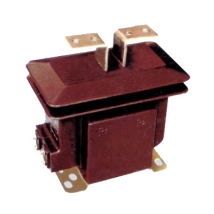
Introduction to the LFS-10 Current Transformer
The LFS-10 is a medium-voltage cast-resin current transformer (CT) engineered for precise current measurement and robust protection functionality in 11kV (IEC standard) or 10kV (domestic system equivalent) power networks. Designed for both indoor switchgear and outdoor pole-mounted applications, this device leverages advanced vacuum pressure impregnation (VPI) epoxy resin technology to deliver superior dielectric integrity, environmental resilience, and long-term operational stability. Unlike traditional oil-immersed CTs, the LFS-10 eliminates fire hazards, reduces maintenance overhead, and offers enhanced mechanical strength—making it ideal for urban substations, industrial facilities, and renewable energy interconnection points.
Operating Principle of Cast-Resin Insulation
Cast-resin insulation in the LFS-10 employs a two-component cycloaliphatic epoxy resin system cured under vacuum and pressure to fully encapsulate the primary conductor, secondary windings, and magnetic core. This VPI process ensures complete void elimination, preventing partial discharge inception even under continuous overvoltage conditions. The resulting monolithic structure provides a dielectric strength exceeding 75 kV (rms) for 1-minute power frequency withstand voltage at the 11kV system level. The resin’s high tracking resistance (CTI > 600 V per IEC 60112) and UV-stabilized formulation enable reliable outdoor deployment without degradation from solar radiation, moisture ingress, or pollution accumulation. Thermal conductivity of ~0.8 W/m·K facilitates efficient heat dissipation during overload events, maintaining core performance within specified accuracy limits.
Advantages Over Oil-Immersed Designs
Compared to oil-filled CTs, the LFS-10 eliminates risks associated with flammable dielectric fluids, making it compliant with stringent fire safety codes in commercial and residential zones. Its solid insulation requires no oil sampling, level monitoring, or gasket replacement—reducing lifecycle costs by up to 40% over a 25-year service life. The absence of breathing mechanisms prevents moisture absorption, ensuring stable insulation resistance (>10,000 MΩ at 20°C) throughout its operational envelope. Additionally, the compact footprint (typically 220 mm height × 180 mm diameter) allows integration into space-constrained ring main units (RMUs) and metal-enclosed switchgear where oil units would be impractical. Mechanical robustness is further enhanced by the resin’s tensile strength (>50 MPa), which resists cracking under seismic loads (up to 0.5g) or thermal cycling (-40°C to +40°C ambient).
Typical Applications Overview
The LFS-10 serves dual roles in metering and protection circuits across diverse infrastructure. In utility substations, it feeds revenue-grade kWh meters with Class 0.2S or 0.5S accuracy signals while simultaneously supplying overcurrent relays (Class 5P or 10P) for fault detection. Industrial plants utilize it for motor protection, harmonic monitoring, and load profiling in 10kV distribution feeders. Renewable integration projects—particularly solar farms and small hydro stations—deploy the LFS-10 at grid interconnection points to meet grid code requirements for fault ride-through and anti-islanding protection. Its low phase displacement (<±10 minutes at rated current) ensures synchronization accuracy in phasor measurement units (PMUs) and digital relay coordination schemes.
Technical Specifications
The LFS-10 adheres to rigorous electrical and environmental parameters defined by international and domestic standards. Below is a comprehensive specification table followed by detailed subsections covering service conditions and performance envelopes.
| Parameter | Value |
|---|---|
| Rated Voltage (Ur) | 11 kV (IEC), 10 kV (GB) |
| System Frequency | 50 Hz / 60 Hz |
| Primary Current Ratings | 50 A to 3000 A (standard); custom up to 4000 A |
| Secondary Current | 1 A or 5 A |
| Accuracy Classes | Metering: 0.2S, 0.5S; Protection: 5P10, 5P20, 10P10, 10P20 |
| Rated Burden | 2.5 VA to 30 VA (per class) |
| Insulation Level (Um/Up/Ud) | 12 kV / 75 kV (LI) / 28 kV (PFWD) |
| Short-Time Thermal Current | 25 kA for 1 s (Ith) |
| Dynamic Withstand Current | 62.5 kA peak (Idyn) |
| Ambient Temperature Range | -40°C to +40°C |
| Altitude Limit | ≤ 1000 m (derating required above) |
| Relative Humidity | ≤ 95% (non-condensing) |
| Core Material | Grain-Oriented Electrical Steel (GOES), CRGO grade |
| Phase Displacement | ≤ ±10′ (minutes) at 100% In, Class 0.2S |
| Ratio Error Tolerance | ±0.2% at 100% In, Class 0.2S |
Standard Service Conditions
The LFS-10 is rated for continuous operation under IEC 60060-defined standard atmospheric conditions: ambient temperature between -40°C and +40°C, relative humidity not exceeding 95% (non-condensing), and installation altitude ≤1000 meters above sea level. At altitudes exceeding 1000 m, the external insulation must be derated by 1% per 100 m increment due to reduced air density affecting creepage distance effectiveness. The transformer is designed for three-phase systems with maximum continuous overvoltage of 1.1 × Ur (12.1 kV) and temporary overvoltages up to 1.3 × Ur for durations ≤8 hours. Pollution severity is classified as Medium (creepage distance ≥20 mm/kV) per IEC 60815, suitable for industrial and coastal environments with periodic washing recommended in high-salinity zones.
Performance Envelope and Accuracy Compliance
Accuracy performance is validated across the full operating range per IEC 61869-2. For Class 0.2S metering, ratio error must remain within ±0.2% and phase displacement within ±10 minutes at 1%, 5%, 20%, 100%, and 120% of rated primary current (In). Protection classes (e.g., 5P20) guarantee composite error ≤5% at 20× In with specified burden. The GOES core exhibits low hysteresis loss (<0.8 W/kg at 1.5 T, 50 Hz) and high permeability (>1500), minimizing excitation current and ensuring linear response during fault transients. Thermal stability is maintained through resin’s coefficient of thermal expansion (CTE ≈ 60 × 10-6/°C), closely matched to copper windings to prevent microcracking during thermal cycling.
Typical Applications
The LFS-10’s versatility enables deployment across multiple segments of the power delivery chain, each demanding specific accuracy, reliability, and environmental resilience characteristics.
Substation Secondary Metering
In 11kV/0.4kV distribution substations, the LFS-10 provides high-fidelity current signals to revenue meters compliant with MID or ANSI C12.20 standards. Installed on outgoing feeders, it typically operates at Class 0.2S with 5 A secondary output feeding multi-tariff kWh meters. The low phase displacement ensures accurate power factor calculation critical for reactive energy billing. For example, in a European utility substation, LFS-10 units with 600/5 A ratio and 10 VA burden supply data to AMI head-end systems, enabling real-time load forecasting and theft detection. The cast-resin housing withstands condensation in unheated cabinets, eliminating errors caused by moisture-induced insulation leakage in older oil designs.
Industrial Power Distribution
Manufacturing facilities with 10kV internal networks use the LFS-10 for motor protection and energy management. A typical 2 MW induction motor circuit employs an LFS-10 rated 400/1 A, Class 5P20, feeding a digital motor protection relay (e.g., Siemens 7UM). During startup inrush (6–8× In), the CT maintains saturation margin due to its high knee-point voltage (>150 V at 5 A secondary). Simultaneously, a parallel 0.5S winding supplies a power quality analyzer for harmonic distortion monitoring (THD <5% per IEEE 519). The compact size allows retrofit into legacy switchgear without busbar modifications, while the resin’s flame retardancy (UL 94 V-0) meets factory safety codes.
Renewable Energy Integration
Solar photovoltaic (PV) plants connecting to 11kV grids deploy LFS-10 CTs at the point of common coupling (PCC) to satisfy grid code requirements. For instance, under China’s GB/T 19964-2012, inverters must disconnect within 2 seconds during islanding—a function verified using LFS-10 signals with <±0.5% ratio error at 20% In. The CT’s fast transient response (rise time <100 µs) captures fault currents during asymmetrical short circuits, enabling anti-islanding relays to operate reliably. Outdoor-rated units endure desert conditions (ambient +55°C with solar loading) thanks to UV-resistant resin additives that prevent chalking or embrittlement over 25 years.
Rural and Suburban Distribution Networks
In remote areas with limited maintenance access, the LFS-10’s maintenance-free design ensures decades of service. Pole-mounted on 10kV overhead lines, it feeds recloser controls and SCADA RTUs for automated sectionalizing. A common configuration uses 200/5 A, Class 10P10 for overcurrent tripping and Class 1.0 for basic metering. The high dynamic withstand (62.5 kA) handles lightning-induced surges without core damage, while hydrophobic resin surfaces shed rain and ice, preventing flashovers during wet-pollution events. Field data from Southeast Asian utilities show >99.5% availability over 10 years, outperforming oil units prone to seal leaks in tropical climates.
Compliance with International Standards
The LFS-10 is engineered to satisfy both global and regional regulatory frameworks, ensuring interoperability and safety across markets.
IEC 61869-2 Certification Details
IEC 61869-2:2012 defines performance, testing, and marking requirements for inductive current transformers. The LFS-10 complies with all clauses, including Clause 6 (rated values), Clause 7 (accuracy requirements), and Clause 12 (type tests). Key validations include temperature rise test (winding ΔT ≤ 60 K above ambient at 1.2× In), short-circuit withstand (25 kA/1s without deformation), and impulse voltage test (75 kV LI with ≤30% residual charge). The manufacturer’s test report includes waveform capture of ratio/phase error across 1–120% In, verified by accredited labs per ISO/IEC 17025. Markings include Ur, Ip/Is, accuracy class, burden, and polarity dots per Clause 15.
Alignment with GB/T 20840.2
China’s GB/T 20840.2-2014 mirrors IEC 61869-2 but adds domestic requirements: mandatory short-time thermal current of 25 kA/1s (vs. IEC’s optional 20–40 kA range), and stricter pollution performance (creepage ≥25 mm/kV for heavy industrial zones). The LFS-10 exceeds these via reinforced sheds and silicone-hydrophobic resin. Notably, GB/T mandates dual accuracy windings for combined metering/protection use—a feature standard on LFS-10 models sold in China. Type testing includes additional salt fog exposure (1000 hours per GB/T 2423.17) to validate outdoor durability.
Differences Between IEC and Domestic Standards
While IEC 61869-2 permits 10kV or 11kV rated voltage based on system grounding, GB/T 20840.2 exclusively references 10kV for Chinese networks. However, the LFS-10’s insulation level (Um=12kV) satisfies both. Another divergence: IEC allows Class 0.2 for metering, whereas GB/T requires Class 0.2S (extended low-current accuracy). The LFS-10 addresses this by offering S-class variants globally. Testing protocols also differ—I EC emphasizes statistical validation of production samples, while GB/T requires 100% routine tests including partial discharge (<10 pC at 1.2× Ur/√3).
On-Site Testing Procedures
Post-installation verification ensures the LFS-10 performs within specifications before energization. All tests follow IEC 61869-2 Annex D and IEEE C57.13 guidelines.
Insulation Resistance Test
Using a 2500 V DC megohmmeter, measure insulation resistance between primary-to-secondary, primary-to-ground, and secondary-to-ground. Acceptance criterion: ≥10,000 MΩ at 20°C. Correct for temperature using RT2 = RT1 × 2(T1-T2)/10. Low readings indicate moisture ingress or resin cracking—requiring drying or replacement. This test is critical after transportation in humid climates.
Turns Ratio Test
Apply low-voltage AC (5–10 V) to secondary winding and measure induced primary voltage. Calculate ratio as Vp/Vs; compare to nameplate (e.g., 600/5 = 120:1). Tolerance: ±0.5% for protection, ±0.2% for metering classes. Use a dedicated turns ratio tester (e.g., Omicron CT Analyzer) for automated comparison. Deviations suggest winding shorts or incorrect tap selection.
Polarity Test
Verify reducing polarity per IEC 61869-2 Figure D.3. Apply DC pulse to primary; observe secondary voltage direction with oscilloscope. Positive-going primary pulse must yield positive secondary at marked terminal. Incorrect polarity causes relay misoperation—e.g., directional overcurrent elements tripping for reverse faults.
Power Frequency Withstand Voltage Test
Apply 28 kV rms (50 Hz) for 1 minute between primary and grounded secondary/core. Monitor for flashover or excessive leakage current (<1 mA). This validates resin integrity post-transportation. Never perform if moisture is suspected—pre-dry at 60°C for 12 hours first.
Short-Circuit Test (for CT)
Inject 10–20× rated current into primary using a portable test set (e.g., Doble F6150). Verify secondary output matches expected value within accuracy class limits. For 5P20, composite error must be ≤5% at 20× In with rated burden. This confirms core non-saturation during faults—critical for protection reliability.
Preventive Maintenance Guide
Though maintenance-free by design, periodic checks extend service life and prevent unexpected failures.
Periodic Inspection Protocol
Annual visual inspection includes checking for resin cracks, surface tracking, terminal corrosion, and mounting hardware tightness. Use UV flashlight to detect corona discharge (purple glow) indicating insulation degradation. Clean housing with deionized water if pollution layer exceeds 0.1 mg/cm² (measured by ESDD/NSDD test). Torque check secondary terminals to 2.5 N·m to prevent heating at connections.
Maintenance Intervals and Fault Diagnosis
Every 5 years, perform insulation resistance and ratio tests regardless of condition. Common faults include:
– High ratio error: Core saturation from DC offset or incorrect burden.
– Low insulation resistance: Moisture ingress at terminal seals—replace gaskets.
– No output: Open secondary circuit (never operate open-circuited!) or broken lead.
Replace unit if partial discharge exceeds 20 pC at operating voltage. Expected service life is 25–30 years with proper maintenance.
| Interval | Action |
|---|---|
| Annually | Visual inspection, cleaning, terminal torque check |
| 5 Years | Insulation resistance, turns ratio, polarity verification |
| After Fault | Full suite of on-site tests plus thermal imaging |
| 10+ Years | Consider replacement if PD >15 pC or IR <5000 MΩ |
Conclusion
The LFS-10 11kV cast-resin current transformer represents a benchmark in medium-voltage instrumentation, combining precision metrology with rugged protection capabilities. Its VPI epoxy resin encapsulation delivers unmatched dielectric strength (75 kV LI withstand), environmental resilience (IP54 rating), and fire safety—addressing critical limitations of legacy oil-immersed designs. Engineered to IEC 61869-2 and GB/T 20840.2, it ensures global compliance while supporting dual metering (Class 0.2S) and protection (5P20) functions in a single compact unit. The GOES core minimizes phase displacement (<±10') and ratio error (±0.2%), enabling accurate revenue billing and reliable relay coordination even under distorted waveforms. With a proven service life of 25–30 years and minimal maintenance requirements, the LFS-10 reduces total cost of ownership across utility, industrial, and renewable applications. Its robust short-circuit withstand (25 kA/1s) and outdoor/indoor versatility make it indispensable for modernizing aging infrastructure or deploying new smart grid assets. For engineers specifying instrumentation in 10/11kV networks, the LFS-10 offers a technically superior, standards-compliant solution that enhances grid safety, measurement integrity, and operational longevity without compromise.