Article Content
Introduction
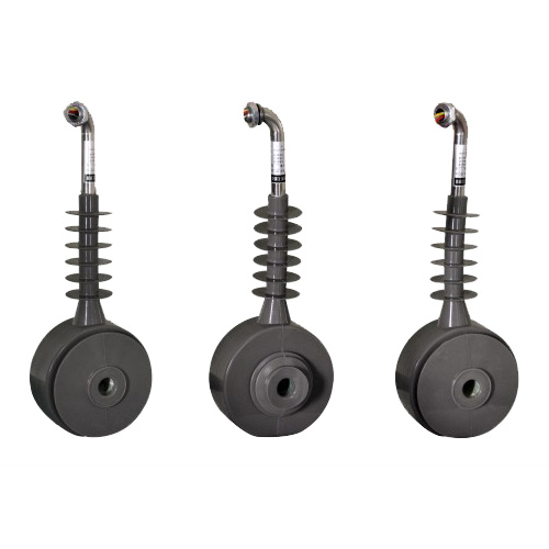
The LJ-ZW32-10 Current Transformer is a high-performance, outdoor-type instrument transformer specifically engineered for accurate current measurement and protection in 10kV medium-voltage power systems. Designed with robust epoxy resin insulation and a compact, maintenance-free structure, this transformer ensures reliable operation under harsh environmental conditions, including high humidity, dust, and temperature fluctuations. Its primary applications include integration into ring main units (RMUs), switchgear assemblies, and distribution substations where precise current monitoring is critical for system protection, metering, and control functions. The LJ-ZW32-10 complies with international standards such as IEC 61869 and GB/T 20840, guaranteeing interoperability and safety across diverse electrical infrastructures. By converting high primary currents into standardized, lower secondary currents (typically 1A or 5A), it enables safe interfacing with protective relays, energy meters, and SCADA systems. This selection guide provides essential technical criteria to assist engineers and system designers in choosing the optimal configuration of the LJ-ZW32-10 for their specific application requirements.
System Voltage
The LJ-ZW32-10 Current Transformer is rated for use in 10kV class power systems, which typically operate within a nominal voltage range of 6kV to 12kV. However, proper selection requires careful consideration of both the system’s nominal voltage and its maximum operating voltage (Um). According to IEC 60038 and national grid codes, the highest voltage for equipment in a 10kV network is usually 12kV. Therefore, the LJ-ZW32-10 is designed with a rated insulation level corresponding to Um = 12kV, ensuring dielectric strength and long-term reliability under transient overvoltages, switching surges, and lightning impulses.
The transformer’s insulation system—comprising cast epoxy resin with hydrophobic properties—provides excellent creepage distance and pollution performance, making it suitable for installation in environments classified as pollution degree III or IV per IEC 60664. For systems with grounded neutrals (effectively or resonantly grounded), the transformer must withstand phase-to-ground voltages continuously. In ungrounded or impedance-grounded systems, temporary phase-to-ground overvoltages during single-line-to-ground faults can reach √3 times the nominal phase voltage; the LJ-ZW32-10 is tested to endure such conditions without insulation failure.
It is critical to match the transformer’s voltage rating with the actual system parameters. Using a 10kV-rated CT on a 20kV system, for example, would risk catastrophic insulation breakdown. Conversely, over-specifying voltage ratings may lead to unnecessary cost and size increases. The table below summarizes key voltage-related specifications:
| Parameter | Value | Standard Reference |
|---|---|---|
| Rated System Voltage (Un) | 10 kV | IEC 60038 |
| Highest Voltage for Equipment (Um) | 12 kV | IEC 61869-3 |
| Lightning Impulse Withstand Voltage (Peak) | 75 kV | IEC 60060-1 |
| Power Frequency Withstand Voltage (RMS, 1 min) | 28 kV | IEC 60270 |
| Minimum Creepage Distance | 240 mm (for 10kV, PD III) | IEC 60815 |
Transformation Ratio
The transformation ratio (or turns ratio) of a current transformer defines the relationship between the primary current (Ip) and the secondary current (Is), expressed as Ip:Is. For the LJ-ZW32-10, standard secondary currents are 1A or 5A, while primary currents range from 50A to 3000A, depending on the application. Selecting the correct ratio is fundamental to ensuring measurement accuracy, relay coordination, and equipment safety.
A key principle in ratio selection is that the normal load current should fall within 20% to 100% of the rated primary current. Operating below 20% may result in poor accuracy due to core magnetization characteristics, especially in metering applications. Conversely, exceeding the rated primary current—even briefly—can cause saturation, leading to distorted secondary waveforms and potential misoperation of protective devices.
The LJ-ZW32-10 often features multiple secondary windings or tap-accessible primaries to provide flexibility. For instance, a unit might be labeled “600–1200/5A,” indicating two selectable ratios via terminal connections. When dual ratios are available, users must ensure proper wiring to avoid open-circuit conditions on unused taps, which could generate dangerous overvoltages.
For protection applications, the ratio must accommodate both normal load and fault currents. A typical design approach uses a primary rating 1.2 to 1.5 times the expected maximum load current. For example, if a feeder carries a peak load of 800A, selecting a 1000/5A or 1200/5A ratio would be appropriate. For metering, tighter alignment with actual load (e.g., 800/5A) improves accuracy but requires verification that short-circuit currents do not exceed the CT’s rated accuracy limit factor (ALF).
Below is a representative table of common transformation ratios offered for the LJ-ZW32-10:
| Primary Current (A) | Secondary Current (A) | Standard Ratios Available | Typical Application |
|---|---|---|---|
| 50 – 200 | 1 or 5 | 50/1, 75/5, 100/5, 150/1, 200/5 | Small transformers, lighting circuits |
| 250 – 800 | 1 or 5 | 300/5, 400/1, 600/5, 800/1 | Distribution feeders, commercial loads |
| 1000 – 2000 | 1 or 5 | 1000/5, 1200/1, 1600/5, 2000/1 | Industrial motors, substation incomers |
| 2500 – 3000 | 1 or 5 | 2500/5, 3000/1 | Large transformers, utility interconnections |
Note: Custom ratios may be available upon request. Always verify thermal and dynamic current ratings alongside ratio selection to ensure mechanical and thermal stability during fault conditions.
Accuracy Class
Accuracy class defines the maximum permissible error in current transformation under specified operating conditions. For the LJ-ZW32-10, accuracy classes are designated separately for metering (e.g., 0.2, 0.5, 1) and protection (e.g., 5P10, 10P20) applications, as defined by IEC 61869-2. Metering classes prioritize precision at low to nominal currents, while protection classes emphasize performance during high overcurrents without saturation.
Metering accuracy classes (0.2, 0.5, etc.) indicate the percentage composite error at rated current and burden. For example, a 0.5-class CT must maintain an error ≤ ±0.5% at 100% In with the specified burden. These are used for revenue metering and energy management where billing accuracy is critical. The LJ-ZW32-10 supports metering classes down to 0.2S (special class for wide-range accuracy from 1% to 120% of In), ideal for applications with highly variable loads.
Protection accuracy classes follow the “Px” notation, where “P” stands for protection, “x” is the composite error percentage (e.g., 5 or 10), and the suffix number indicates the rated accuracy limit factor (ALF). For instance, 5P20 means the CT will maintain ≤5% error when subjected to 20 times the rated primary current, provided the connected burden does not exceed the rated value. Selecting the correct ALF is crucial: if the actual fault current is 15 kA and the CT ratio is 1000/5A (In = 1000A), the required ALF is at least 15 (15,000 ÷ 1,000). Choosing 5P10 in this case would lead to saturation and relay misoperation.
The table below outlines typical accuracy classes supported by the LJ-ZW32-10 and their recommended uses:
| Accuracy Class | Max Composite Error | Test Conditions | Primary Application |
|---|---|---|---|
| 0.2S | ±0.2% | 1%, 5%, 20%, 100%, 120% In | Precision revenue metering |
| 0.5 | ±0.5% | 100% In | General metering, sub-billing |
| 1 | ±1.0% | 100% In | Monitoring, non-critical metering |
| 5P10 | ±5% | 10 × In, rated burden | Overcurrent protection (low ALF) |
| 5P20 | ±5% | 20 × In, rated burden | Standard feeder protection |
| 10P20 | ±10% | 20 × In, rated burden | Backup protection, cost-sensitive designs |
When specifying accuracy, always consider the total burden imposed by connected devices (relays, meters, wiring resistance). Exceeding the rated burden degrades accuracy and may invalidate the stated class performance.
5. Burden Calculation
The burden of a current transformer (CT) is the total impedance presented to its secondary winding, comprising the connected relay(s), wiring resistance, and any other components in the secondary circuit. Accurate burden calculation is essential to ensure the CT operates within its accuracy class and does not saturate under normal or fault conditions.
Burden is typically expressed in volt-amperes (VA) at a specified secondary current (usually 1 A or 5 A). The total burden \( Z_b \) can be calculated using:
\[
Z_b = \frac{VA_{total}}{I_s^2}
\]
where \( I_s \) is the secondary current.
The total VA burden includes contributions from:
- Relay burden (\( VA_{relay} \))
- Lead wire resistance (\( R_{lead} \))
- Connection resistances (often negligible but included for precision)
For copper conductors, lead resistance is calculated as:
\[
R_{lead} = \rho \cdot \frac{L}{A}
\]
where \( \rho = 0.0178 \, \Omega \cdot mm^2/m \) (resistivity of copper at 20°C), \( L \) is the one-way length in meters, and \( A \) is the cross-sectional area in mm². Since current flows to and from the relay, the total lead resistance is \( 2 \times R_{lead} \).
| Component | Typical Burden (VA @ 5A) | Impedance (Ω) | Notes |
|---|---|---|---|
| Numerical Relay | 0.25 – 1.0 | 0.01 – 0.04 | Low burden due to high-input impedance electronics |
| Electromechanical Relay | 2.5 – 12.5 | 0.1 – 0.5 | Higher burden; varies with design |
| 2.5 mm² Copper Wire (100 m round-trip) | ≈3.56 | 0.142 | \( R = 2 \times 0.0178 \times 100 / 2.5 = 1.424 \, \Omega \); \( VA = I^2R = 25 \times 1.424 ≈ 35.6 \, VA \) — Correction: actual VA = 5² × 0.142 = 3.55 VA |
| Total Allowable Burden (Class 5P10, 15 VA) | ≤15 | ≤0.6 | Must not exceed CT rating |
Note: Always verify that the calculated total burden is less than the CT’s rated burden at the specified accuracy class. Exceeding this limit may cause ratio errors or saturation during faults.
6. Short-Circuit Considerations
Current transformers must withstand both thermal and mechanical stresses during system short-circuit events. The CT’s performance during such transients directly impacts protection relay operation and system safety.
Key parameters include:
- Symmetrical short-circuit current (\( I_{sc} \)): RMS value of AC component.
- Asymmetrical (DC offset) current: Can reach up to twice the symmetrical value, depending on X/R ratio.
- Duration of fault (\( t \)): Typically 0.1–3 seconds, based on protection clearing time.
The CT must satisfy two main criteria:
- Thermal Withstand: The CT must endure \( I_{th}^2 t \leq I_{sc}^2 t_{fault} \), where \( I_{th} \) is the rated short-time thermal current (e.g., 20× rated for 1s).
- Accuracy Limit Factor (ALF): For protection CTs (e.g., 5P or 10P), ALF defines the multiple of rated current up to which the CT maintains specified accuracy. For example, a 5P20 CT remains accurate up to 20× rated current.
If the prospective fault current exceeds the CT’s ALF multiplied by its rated current, the core may saturate, leading to distorted secondary current and potential relay misoperation.
| Parameter | Symbol | Typical Value | Design Check |
|---|---|---|---|
| Rated Primary Current | \( I_{pr} \) | 1000 A | Given by system load |
| Max Fault Current | \( I_{sc} \) | 25,000 A | From system study |
| Required ALF | — | 25 | \( I_{sc}/I_{pr} = 25,000/1000 = 25 \) |
| Selected CT Class | — | 5P20 | Insufficient—requires 5P25 or higher |
| Thermal Withstand | \( I_{th} \) | 20× for 1s | Check \( I_{sc}^2 t_{fault} \leq (20 I_{pr})^2 \times 1 \) |
Remedial actions for inadequate ALF include using a CT with higher ALF, reducing secondary burden, or selecting a larger core size. Always coordinate CT selection with system short-circuit studies.
7. Environmental Considerations
Environmental factors significantly influence CT selection, installation, and long-term reliability. These include temperature extremes, humidity, altitude, pollution, and seismic activity.
Ambient Temperature: Standard CTs are rated for –5°C to +40°C. For outdoor or harsh environments (e.g., deserts, arctic regions), extended temperature ratings (–40°C to +55°C) may be required. High temperatures reduce insulation life, while low temperatures can embrittle materials.
Altitude: Above 1000 meters, air density decreases, reducing dielectric strength and cooling efficiency. For every 100 m above 1000 m, derating of 1–1.5% is typically applied to voltage and current ratings.
Pollution and Humidity: In coastal or industrial areas, salt spray or chemical contaminants can degrade insulation and cause tracking. CTs should have appropriate IP (Ingress Protection) ratings—e.g., IP54 for indoor dusty environments, IP65 or higher for outdoor use.
Seismic Requirements: In earthquake-prone zones, CTs must comply with seismic standards (e.g., IEEE 693 or IEC 60068-2-57). This often involves reinforced mounting and reduced center of gravity.
| Environment | Key Concerns | Recommended CT Features |
|---|---|---|
| Indoor Substation | Moderate temp, low pollution | Standard epoxy resin, IP20 |
| Coastal Outdoor | High humidity, salt corrosion | Stainless steel hardware, silicone rubber housing, IP66 |
| High Altitude (>2000 m) | Reduced cooling, lower dielectric strength | Derated current rating, increased creepage distance |
| Cold Climate (<–25°C) | Material brittleness, ice loading | Low-temp composite materials, heated enclosures if needed |
| Seismic Zone (PGA >0.3g) | Mechanical shock, vibration | Anchored base, dynamic testing per IEEE 693 |
Always consult local standards (e.g., IEC 61869, IEEE C57.13) and site-specific environmental data during specification.
8. CT Selection and Verification Checklist
Use this checklist during design, procurement, and commissioning to ensure all critical aspects of CT application are addressed.
| # | Check Item | Verified? (Y/N) | Remarks |
|---|---|---|---|
| 1 | Primary current rating matches max continuous load | e.g., 125% of normal load | |
| 2 | Accuracy class appropriate for application (metering vs. protection) | Metering: 0.2/0.5; Protection: 5P/10P | |
| 3 | Total secondary burden ≤ CT rated burden | Include leads, relays, connections | |
| 4 | ALF ≥ (Max fault current / Rated primary current) | Apply safety margin (e.g., 10–20%) | |
| 5 | Thermal withstand capability sufficient for fault duration | Check \( I_{th}^2 t \) rating | |
| 6 | Environmental rating suitable for installation location | IP, temp, altitude, seismic | |
| 7 | Secondary wiring uses correct conductor size and routing | Avoid sharp bends, minimize length | |
| 8 | CT polarity marked and verified during commissioning | Critical for differential schemes | |
| 9 | Grounding of CT secondary circuit implemented per code | Single-point grounding at relay panel | |
| 10 | Type test certificates available (IEC 61869 / IEEE C57.13) | Confirm compliance |
This checklist should be completed jointly by protection engineers, project managers, and commissioning teams. Any “No” response requires corrective action before energization.