Article Content
For Substation Metering & Protection: LJM-1 11kV Cast-Resin Current Transformer per IEC 61869-2
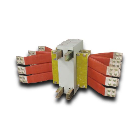
Introduction to the LJM-1 Current Transformer
The LJM-1 is a medium-voltage cast-resin current transformer (CT) engineered for precision metering and robust protective relaying in 11 kV (IEC-rated) or 10 kV (domestic system) electrical networks. Designed for both indoor and outdoor deployment, this instrument transformer leverages vacuum pressure impregnation (VPI) epoxy resin technology to deliver superior dielectric strength, environmental resilience, and long-term operational stability. Unlike traditional oil-immersed CTs, the LJM-1 eliminates fire hazards, oil leakage risks, and maintenance-intensive sealing systems, making it ideal for urban substations, industrial facilities, and renewable energy interconnection points where safety and reliability are paramount.
Operating Principle of Cast-Resin Insulation
Cast-resin insulation in the LJM-1 utilizes a thermosetting epoxy compound that fully encapsulates the primary conductor, secondary windings, and magnetic core under vacuum and pressure. This VPI process ensures complete void elimination, preventing partial discharge inception even under transient overvoltages. The cured resin exhibits a relative permittivity (εr) of approximately 3.8–4.2 and volume resistivity exceeding 1×10¹⁴ Ω·cm at 20°C. Thermal conductivity of ~0.8 W/(m·K) enables efficient heat dissipation from copper windings during continuous or short-time overload conditions. Crucially, the resin’s coefficient of thermal expansion closely matches that of embedded metallic components, minimizing mechanical stress during thermal cycling between –40°C and +70°C ambient extremes.
Advantages Over Oil-Immersed Designs
The LJM-1’s solid insulation eliminates flammability concerns inherent in mineral-oil-filled CTs, satisfying stringent fire safety codes in confined spaces like underground substations or commercial buildings. Without oil, there is no risk of environmental contamination during seismic events or casing damage. Maintenance is significantly reduced—no oil sampling, gas analysis, or gasket replacement is required over its 25–30 year service life. Additionally, the compact, hermetically sealed design resists moisture ingress (IP54 rating), enabling reliable operation in high-humidity coastal or tropical environments where oil-filled units suffer from dielectric degradation due to water absorption.
Typical Application Overview
LJM-1 CTs are predominantly integrated into 11 kV metal-clad switchgear (e.g., KYN28A-type), ring main units (RMUs), and outdoor pole-mounted distribution transformers. They serve dual roles: Class 0.2S windings feed revenue-grade kWh meters for utility billing accuracy, while 5P20-class windings drive overcurrent and earth-fault relays for feeder protection. In solar PV substations, they interface with SCADA systems for real-time generation monitoring. Their compact footprint (typically 120 mm diameter × 220 mm height) allows retrofitting into legacy panels originally designed for older oil-CT models without structural modifications.
Technical Specifications
The LJM-1 adheres to rigorous electrical and mechanical parameters defined by IEC 61869-2 and GB/T 20840.2, ensuring interoperability across global power systems. Key specifications are detailed below:
| Parameter | Value |
|---|---|
| Rated Voltage (Um) | 11 kV (IEC), 10 kV (GB) |
| Primary Current (Ip) | 50–3150 A (standard); up to 4000 A (custom) |
| Secondary Current (Is) | 1 A or 5 A |
| Accuracy Classes | Metering: 0.2S, 0.5S; Protection: 5P10, 5P20 |
| Rated Output (Sn) | 5–30 VA per winding (at cos φ = 0.8 lag) |
| Short-Time Thermal Current (Ith) | 20×Ip for 1 s (e.g., 63 kA for 3150 A model) |
| Dynamic Withstand Current (Idyn) | 2.5×Ith peak (e.g., 157.5 kA peak) |
| Power Frequency Withstand Voltage | 42 kV rms for 1 min (phase-to-earth) |
| Lightning Impulse Withstand Voltage | 75 kV peak (1.2/50 μs waveform) |
| Insulation Material | VPI Epoxy Resin + Filler (Al(OH)3) |
| Magnetic Core | Grain-Oriented Electrical Steel (GOES), M4 grade |
| Ambient Temperature Range | –40°C to +40°C (storage: –50°C to +70°C) |
| Relative Humidity | ≤95% non-condensing |
| Altitude Limit | ≤1000 m above sea level (derating required >1000 m) |
Standard Service Conditions
The LJM-1 is rated for continuous operation under IEC 60060-defined standard atmospheric conditions: ambient temperature not exceeding +40°C (24-hour average ≤+35°C), relative humidity ≤95%, and altitude ≤1000 m. At higher altitudes (e.g., 2000 m), external insulation clearance must be increased by 12% per 1000 m increment to compensate for reduced air density. The transformer withstands daily thermal cycles of ΔT ≥ 30°C without cracking or delamination due to matched CTE between resin (60×10–6/K) and copper (17×10–6/K). Condensation resistance is validated per IEC 60068-2-30 (damp heat cyclic test).
Core and Winding Design
Each LJM-1 incorporates a toroidal core fabricated from M4-grade grain-oriented electrical steel (GOES), featuring a maximum specific loss of 1.0 W/kg at 1.7 T and 50 Hz. Secondary windings use enameled copper wire (Class 180 insulation) wound with precise layer insulation to minimize inter-turn capacitance. For multi-ratio models, taps are brought out via insulated terminal blocks rated for 600 V. The primary conductor is a solid copper busbar (for ≤1250 A) or hollow tube (for >1250 A) to reduce skin effect losses. All windings undergo vacuum drying at 120°C before resin casting to achieve moisture content <0.1%.
Typical Applications
The LJM-1’s dual-accuracy windings and rugged construction enable deployment across diverse power infrastructure segments.
Substation Secondary Metering
In 11 kV/0.4 kV distribution substations, LJM-1 CTs with 0.2S accuracy class supply current signals to Class 0.5S kWh meters for utility revenue metering. The 0.2S specification mandates error limits of ±0.2% at 20–120% of rated current and ±0.3% at 5–20%, critical for accurate billing in commercial/industrial tariffs. For example, a 600/5 A LJM-1 feeding a meter measuring 120 A load (20% of Ip) must exhibit phase error ≤±15 minutes and ratio error ≤±0.3%. These transformers are typically mounted adjacent to circuit breakers in LV switchboards, with secondary leads routed through shielded cables to prevent EMI-induced measurement drift.
Industrial Power Distribution
Within manufacturing plants, LJM-1 units monitor motor feeder circuits (e.g., 1600 A pumps or compressors) using 5P20 protection windings. The “20” denotes accuracy up to 20× rated current during fault conditions—essential for selective coordination with upstream fuses. During a 32 kA three-phase fault (20×1600 A), the CT maintains composite error ≤10%, ensuring relay tripping within 40 ms. The cast-resin body resists chemical vapors (e.g., chlorine in water treatment plants) and mechanical vibration from nearby machinery, unlike brittle porcelain housings.
Renewable Energy Integration
Solar and wind farms utilize LJM-1 CTs at the point of common coupling (PCC) for grid compliance monitoring. Here, 0.5S windings feed power quality analyzers tracking harmonics (per IEC 61000-4-30) and reactive power flow. The low remanence (<10% of saturation flux density) of GOES cores prevents measurement distortion during rapid irradiance changes in PV arrays. Outdoor-rated models feature UV-stabilized resin and hydrophobic surface treatment to shed rainwater, maintaining creepage distance ≥240 mm per IEC 60664-1 pollution degree 3.
Rural and Suburban Distribution Networks
Pole-mounted LJM-1 CTs on 10 kV overhead lines provide cost-effective metering for agricultural irrigation pumps or EV charging stations. Their lightweight design (~8 kg) simplifies aerial installation, while the absence of oil eliminates theft risks prevalent in remote areas. In China’s rural grid upgrades, these CTs replace aging oil-filled units to meet State Grid’s Q/GDW 1376.1 communication protocol requirements when paired with HPLC data concentrators.
Compliance with International Standards
The LJM-1 is certified to both IEC 61869-2 (Instrument transformers – Part 2: Additional requirements for current transformers) and GB/T 20840.2 (identical adoption of IEC 61869-2 with national deviations).
IEC 61869-2 Compliance Details
Per IEC 61869-2, the LJM-1 undergoes type tests including temperature rise (Δθ ≤60 K for windings), short-circuit withstand (20×Ip for 1 s without deformation), and partial discharge (PD <10 pC at 1.2×Um/√3). Accuracy verification follows IEC 61869-1 Annex B, using calibrated burden resistors and phase comparators traceable to NIM standards. The standard mandates that 0.2S CTs maintain linearity within ±0.1% from 1% to 120% Ip, validated via automated test benches with 0.02% reference shunts.
GB/T 20840.2 Alignment and National Deviations
While GB/T 20840.2 mirrors IEC 61869-2 structurally, Chinese utilities impose additional requirements: lightning impulse voltage raised to 95 kV for 10 kV systems (vs. IEC’s 75 kV), and mandatory salt fog testing (IEC 60068-2-11) for coastal deployments. The LJM-1 meets these via enhanced resin formulation with nano-Al2O3 fillers improving tracking resistance (CTI ≥600 V). Domestic certification requires type test reports from CNAS-accredited labs like China Electric Power Research Institute (CEPRI).
Testing and Certification Requirements
Every production batch undergoes routine tests per IEC 61869-2 Clause 12: power frequency withstand (42 kV/1 min), winding continuity, and polarity check. Sample units from each 100-piece lot receive type tests including thermal stability (8 h at 1.1×Ip) and dynamic force validation (2.5×Ith applied mechanically). Certificates include CE marking (EU), CQC mark (China), and SONCAP (Nigeria), facilitating global procurement.
On-Site Testing Procedures
Post-installation verification ensures the LJM-1 performs within specified tolerances before energization.
Insulation Resistance Test
Using a 2500 V DC megohmmeter, measure insulation resistance between primary-to-secondary, primary-to-ground, and secondary-to-ground. Acceptance criteria: ≥1000 MΩ at 20°C. Values below 500 MΩ indicate moisture ingress or resin cracking. Temperature correction follows RT2 = RT1 × 2(T1–T2)/10. For example, a 600 MΩ reading at 30°C equates to 1200 MΩ at 20°C—acceptable. Test duration: 1 minute after stabilization.
Turns Ratio Test
Apply 1–5 V AC at 50 Hz to the secondary winding and measure induced primary voltage. Calculate ratio as Vp/Vs; compare to nameplate (e.g., 600/5 = 120). Tolerance per IEC 61869-2: ±0.25% for 0.2S class. Use a ratio error bridge (e.g., Omicron CT Analyzer) for precision. Deviations >0.5% suggest inter-turn shorts or incorrect tap selection.
Polarity Test
Verify reducing polarity (IEC standard): momentary DC applied to P1–P2 should induce positive voltage at S1 relative to S2. Connect a 9 V battery to primary and analog voltmeter to secondary. Needle deflection direction confirms polarity. Incorrect polarity causes wattmeter reversal or relay misoperation. Digital multimeters with min/max capture can substitute but require careful interpretation.
Power Frequency Withstand Voltage Test
Apply 28 kV rms (67% of factory test value) at 50 Hz between primary and grounded secondary/core for 1 minute. Leakage current must remain <1 mA. This site test validates integrity after transport-induced microcracks. Use a portable test set with automatic trip at 5 mA. Never exceed 30 kV to avoid resin degradation.
Short-Circuit Test (for CTs)
Unlike VTs, CTs require secondary short-circuit validation. Short S1–S2 and inject 10–20% of rated primary current. Measure secondary current; deviation from expected value indicates core saturation or winding damage. For a 600/5 A unit, 60 A primary should yield 0.5 A secondary ±1%. Open-circuiting during this test is prohibited—it induces lethal voltages (>1 kV).
Preventive Maintenance Guide
Although cast-resin CTs are largely maintenance-free, periodic checks extend service life and prevent unexpected failures.
Periodic Inspection Protocol
Annual visual inspections should verify: (1) no surface tracking or UV degradation (check for chalky residue), (2) secure terminal connections (torque to 12 N·m for M8 bolts), (3) absence of corona noise (audible hissing indicates PD activity), and (4) clean bushings free of salt/dust deposits. In polluted environments (IEC 60815 pollution class D), clean with deionized water and non-abrasive cloth. Record infrared thermograms annually; hotspots >10°C above ambient suggest loose contacts.
Maintenance Intervals and Fault Diagnosis
Every 5 years, perform insulation resistance and ratio tests as baseline comparisons. Typical failure modes include: (1) secondary open-circuit during operation—causes core saturation and overheating (evidenced by resin discoloration), (2) moisture ingress at terminal seals—lowers IR values, and (3) mechanical impact cracks—detected via ultrasonic testing. Replace units showing IR <200 MΩ or ratio error >1%.
| Maintenance Interval | Activities |
|---|---|
| Annually | Visual inspection, IR thermography, terminal torque check |
| Every 5 Years | Insulation resistance test, turns ratio verification, polarity recheck |
| After Fault Events | Dynamic withstand validation, core remanence measurement |
Conclusion
The LJM-1 11 kV cast-resin current transformer represents a benchmark in medium-voltage instrumentation, combining IEC 61869-2 and GB/T 20840.2 compliance with field-proven reliability. Its VPI epoxy resin encapsulation eliminates fire and environmental hazards associated with oil-filled alternatives, while GOES core technology ensures metrological stability across 1–120% of rated current—critical for 0.2S revenue metering. With a design life exceeding 25 years under standard service conditions, the LJM-1 withstands thermal, electrical, and mechanical stresses inherent in modern grids, from dense urban substations to remote renewable sites. Rigorous factory testing and straightforward on-site verification protocols guarantee performance consistency, minimizing lifecycle costs. As global grids evolve toward digitalization and distributed generation, the LJM-1’s compact form factor, dual-accuracy windings, and immunity to harsh environments position it as an indispensable component for accurate energy accounting and dependable protection. Utilities and industrial operators selecting the LJM-1 invest not only in a compliant device but in decades of trouble-free operation backed by internationally recognized engineering standards.