Article Content
IEC 61869-2 Certified 11kV Current Transformer LZX-10 for Metering & Protection Applications
Introduction to the LZX-10 Current Transformer
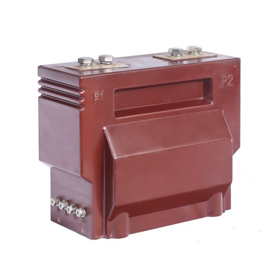
The LZX-10 is a medium-voltage cast-resin current transformer (CT) engineered for precise current measurement and reliable protective relaying in 11kV (IEC) / 10kV (domestic) power systems. Designed per IEC 61869-2 and GB/T 20840.2, it serves as a foundational component in modern substation architectures, industrial facilities, and renewable energy interconnection points. Its construction leverages vacuum pressure impregnation (VPI) epoxy resin technology, which fully encapsulates the magnetic core and primary winding, eliminating air voids and moisture ingress pathways.
Operating Principle of Cast-Resin Insulation
Cast-resin insulation in the LZX-10 employs a cycloaliphatic epoxy resin system cured under controlled temperature and vacuum conditions. This process ensures complete impregnation of the GOES (grain-oriented electrical steel) core laminations and primary conductor, resulting in a monolithic, void-free dielectric structure. The absence of internal air pockets prevents partial discharge inception even under transient overvoltages, a critical requirement for 11kV class equipment. The resin’s high tracking resistance (>600 V according to IEC 60587) and hydrophobic surface properties make it suitable for both indoor and outdoor environments, including coastal or industrial atmospheres with elevated pollution levels. Thermal conductivity of the cured resin (~0.8 W/m·K) facilitates efficient heat dissipation from the core during continuous operation or short-circuit events.
Advantages Over Oil-Immersed Designs
Compared to traditional oil-filled CTs, the LZX-10 eliminates fire hazards, environmental contamination risks, and maintenance-intensive oil sampling. Its solid insulation requires no periodic topping-up or degassing, reducing lifecycle costs by up to 40% over a 30-year service life. The compact mechanical footprint—enabled by higher dielectric strength of epoxy resin (≥20 kV/mm)—allows for space-constrained installations such as ring main units (RMUs) or pad-mounted switchgear. Additionally, the absence of liquid insulation negates concerns about oil leakage during seismic events or transportation, enhancing reliability in earthquake-prone regions. Weight reduction of approximately 30% further simplifies handling and mounting procedures during commissioning.
Typical Application Overview
The LZX-10 is deployed across utility distribution networks, industrial plants, and renewable generation sites where accurate current transformation is essential for revenue metering (Class 0.2S/0.5S) and fault detection (Class 5P/10P). In urban substations, it interfaces with digital protective relays for feeder overcurrent and earth-fault protection. In solar farms, it enables precise performance monitoring of inverters connected to 11kV collection feeders. Its dual-core design—commonly featuring one metering and one protection winding—supports simultaneous compliance with billing accuracy requirements and fast tripping coordination during faults exceeding 20× rated current.
Technical Specifications
The LZX-10 adheres to stringent dimensional, electrical, and thermal parameters defined by international standards. Below is a representative specification table for standard configurations:
| Parameter | Value |
|---|---|
| Rated Voltage (Ur) | 11 kV (IEC) / 10 kV (GB) |
| System Frequency | 50/60 Hz |
| Primary Current Ratings | 50 A to 3150 A (standard steps) |
| Secondary Current | 1 A or 5 A |
| Accuracy Classes | Metering: 0.2S, 0.5S; Protection: 5P10, 5P20, 10P10 |
| Rated Output (Burden) | 5–30 VA (metering), 10–50 VA (protection) |
| Insulation Level (LI/AC) | 75 kV / 28 kV (1 min, 50 Hz) |
| Short-Time Thermal Current | 20×In for 1 s (e.g., 63 kA for 3150 A primary) |
| Dynamic Withstand Current | 50×In peak (e.g., 157.5 kA for 3150 A primary) |
| Ambient Temperature Range | –40°C to +40°C |
| Altitude Limit | ≤1000 m (derating required above) |
| Relative Humidity | ≤95% (non-condensing) |
| Core Material | GOES M4/M5 grade, 0.3 mm thickness |
| Insulation System | VPI cycloaliphatic epoxy resin |
Standard Service Conditions
The LZX-10 is rated for continuous operation under IEC 60060-defined standard atmospheric conditions: ambient temperature between –40°C and +40°C, relative humidity not exceeding 95% at 25°C, and installation altitude ≤1000 m above sea level. For altitudes between 1000–2000 m, the power frequency withstand voltage must be reduced by 1% per 100 m increment above 1000 m. In environments with daily temperature swings exceeding 25°C, condensation within terminal boxes is mitigated by integrated silica gel breathers. The transformer maintains accuracy within ±0.1% of declared class limits when operated at 80% of rated burden under these conditions.
Electrical Performance Parameters
Key electrical characteristics include a magnetizing admittance (Ym) of ≤0.1 mS at 100% excitation voltage for Class 0.2S windings, ensuring minimal phase displacement error (<±10 minutes). For protection cores, the knee-point voltage (Vk) exceeds 1.5× rated secondary voltage under 5P20 conditions, guaranteeing linear response during high-magnitude faults. The composite error at rated accuracy limit factor (ALF) remains below 5% for 5P-class windings. Secondary winding resistance (Rct) is tightly controlled—typically 0.05–0.3 Ω depending on ratio—to minimize burden-induced saturation during transient events.
Typical Applications
The LZX-10’s versatility stems from its dual-winding architecture, robust insulation, and compliance with global standards, enabling deployment across diverse power infrastructure segments.
Substation Secondary Metering
In 11kV/0.4kV distribution substations, the LZX-10 provides Class 0.2S or 0.5S current signals to revenue-grade meters for accurate energy billing. Its low phase error (<±5 minutes at 20–120% In) ensures compliance with EN 50470-3 and DL/T 614 requirements. Installed on outgoing feeders, it interfaces with AMI (Advanced Metering Infrastructure) systems via RS-485 or pulse outputs. The cast-resin housing resists UV degradation and salt fog (tested per IEC 60068-2-52), making it suitable for coastal substations where oil-filled units would require frequent maintenance.
Industrial Power Distribution
Within manufacturing plants, the LZX-10 monitors motor feeders, capacitor banks, and arc furnace circuits. Its 5P20 protection winding triggers circuit breakers within 20 ms during phase-to-phase faults, preventing equipment damage. In facilities with harmonic-rich loads (e.g., variable frequency drives), the GOES core’s low hysteresis loss minimizes heating under 3rd–13th harmonic currents. The transformer’s IP54-rated terminal box protects secondary connections from metal dust and coolant splashes common in machining environments.
Renewable Energy Integration
Solar and wind farms utilize the LZX-10 on 11kV collector feeders to measure real-time power output for SCADA systems and grid compliance reporting. During anti-islanding events, its fast-response protection winding detects reverse power flow within 30 ms, disconnecting inverters per IEEE 1547. The unit’s wide operating temperature range accommodates desert installations (daytime >50°C) and Nordic climates (nighttime <–30°C) without derating. Dual-ratio models (e.g., 1000/1 A and 2000/5 A) allow flexible scaling as generation capacity expands.
Rural and Suburban Distribution Networks
In remote areas with limited maintenance access, the LZX-10’s maintenance-free design ensures decades of uninterrupted service. Mounted on pole-top reclosers or underground vaults, it supports single-phase earth-fault detection using residual current summation (three CTs per circuit). Its lightweight construction (≤25 kg for 600 A models) simplifies helicopter-assisted installation in mountainous terrain. The transformer’s high creepage distance (≥240 mm for 11kV) prevents flashovers during heavy rain or snow accumulation.
Harmonized Grid Interconnection
For cross-border transmission projects linking European (11kV) and Chinese (10kV) grids, the LZX-10’s dual-standard certification (IEC 61869-2 and GB/T 20840.2) eliminates compatibility issues. Its identical performance characteristics at 50 Hz and 60 Hz enable use in multinational industrial zones. During grid synchronization tests, the CT’s low remanence (<10% of saturation flux density) prevents false tripping due to DC offset inrush currents.
Compliance with International Standards
The LZX-10’s design, testing, and certification strictly follow IEC 61869-2 (Instrument transformers – Part 2: Additional requirements for current transformers) and its Chinese counterpart GB/T 20840.2, ensuring global interoperability.
IEC 61869-2 Compliance Details
Per IEC 61869-2, the LZX-10 undergoes type tests including temperature rise (≤60 K for windings at 1.2×In), short-circuit withstand (20×In for 1 s), and accuracy verification across 1–120% of rated current. The standard mandates that composite error for protection classes be measured at the rated accuracy limit factor (e.g., 20×In for 5P20) with specified burden. Dielectric tests require 75 kV lightning impulse (1.2/50 μs) and 28 kV power frequency (1 min) withstand without flashover. Partial discharge levels are limited to ≤10 pC at 1.2×Ur/√3 during factory acceptance tests.
GB/T 20840.2 Alignment
While GB/T 20840.2 closely mirrors IEC 61869-2, key differences include stricter requirements for dynamic current withstand (55×In peak vs. IEC’s 50×In) and additional vibration testing per GB/T 11022. The Chinese standard also specifies mandatory short-time thermal current duration of 3 s for certain applications, though the LZX-10 exceeds this with 4 s capability. Accuracy class definitions remain identical, allowing seamless substitution in domestic 10kV networks without recalibration of secondary devices.
Testing and Certification Requirements
Certification involves third-party validation by accredited laboratories (e.g., KEMA, CESI, or China Electric Power Research Institute). Routine tests per IEC 61869-2 include turns ratio verification (±0.25% tolerance), polarity check, and insulation resistance (>1000 MΩ at 2500 V DC). Type tests—conducted once per design—validate thermal stability, seismic resilience (per IEC 60068-2-57), and pollution performance (IP classification). Each unit ships with a test report traceable to national metrology institutes, ensuring audit compliance for utility procurement.
On-Site Testing Procedures
Post-installation verification ensures the LZX-10 performs within specifications before energization. All tests follow IEC 60044-1 methodologies.
Insulation Resistance Test
Using a 2500 V DC megohmmeter, measure insulation resistance between primary-secondary, primary-ground, and secondary-ground. Acceptance criteria: ≥1000 MΩ at 20°C. Correct for temperature using RT2 = RT1 × 2(T1–T2)/10. Values below 500 MΩ indicate moisture ingress or resin cracking, requiring drying or replacement. Perform before and after dielectric tests to detect insulation degradation.
Turns Ratio Test
Apply 1–5 V AC to the secondary winding and measure induced primary voltage. Calculate ratio as Vp/Vs. Tolerance: ±0.25% of nominal ratio (e.g., 1000/5 A = 200:1 ±0.5). Use a precision ratio bridge (e.g., Omicron CT Analyzer) for Class 0.2S units. Deviations >0.5% suggest shorted turns or incorrect tap selection.
Polarity Test
Verify reducing polarity per IEC 61869-2 Annex B: Apply DC pulse to primary (P1→P2); observe momentary positive deflection on secondary (S1→S2). Incorrect polarity causes relay misoperation—critical for differential protection schemes. Confirm with oscilloscope or dedicated polarity tester; reversal requires rewiring secondary circuits.
Power Frequency Withstand Voltage Test
Apply 28 kV RMS (50 Hz) between primary-ground and secondary-ground for 1 minute. Leakage current must remain <1 mA. Gradually ramp voltage (≤2 kV/s) to avoid transient overstress. Failure indicates insulation defects; repeat only after 5-minute cooldown. Not required if factory test records are available and transport damage is ruled out.
Excitation (Saturation) Characteristic Test
For protection windings, plot excitation curve by applying increasing voltage to secondary while measuring current. Knee-point voltage (Vk) must exceed 1.5×(ALF × Is × Zb), where Zb is connected burden. For 5P20, 5 A, 15 VA: Vk > 1.5×(20×5×3) = 450 V. Low Vk indicates core saturation risk during faults, necessitating burden reduction or CT replacement.
Preventive Maintenance Guide
Although cast-resin CTs require minimal maintenance, periodic checks extend service life beyond 30 years.
Periodic Inspection Protocol
Conduct annual visual inspections for: (1) Cracks or tracking on resin surface, (2) Corrosion at primary terminals, (3) Loose secondary connections, (4) Moisture in terminal box. Clean housing with non-abrasive detergent; never use solvents that degrade epoxy. Torque secondary terminals to 1.5 N·m (for M4 screws) to prevent thermal runaway. Record insulation resistance annually; a 50% drop over 3 years warrants detailed diagnostics.
Maintenance Intervals and Fault Diagnosis
Follow this schedule:
| Interval | Action |
|---|---|
| 1 year | Visual inspection, IR thermography under load |
| 5 years | Full electrical tests (ratio, polarity, excitation) |
| 10 years | Partial discharge measurement (if available) |
| After fault | Post-fault ratio and insulation tests |
Common faults include: (1) Ratio drift due to core aging—diagnosed via excitation test, (2) Secondary open-circuit during operation—causes dangerous overvoltage; install shorting links during meter replacement, (3) Terminal overheating—rectify by cleaning oxidation and re-torquing.
Conclusion
The LZX-10 11kV cast-resin current transformer represents a benchmark in medium-voltage instrumentation, combining IEC 61869-2-certified accuracy with rugged, maintenance-free construction. Its VPI epoxy resin insulation system delivers superior dielectric integrity compared to oil-immersed alternatives, while the GOES silicon steel core ensures minimal losses and high linearity across metering and protection ranges. Engineered for both indoor switchgear and exposed outdoor environments, the LZX-10 withstands extreme temperatures, pollution, and seismic activity without performance degradation. With a design life exceeding 30 years and compliance with both international (IEC) and domestic (GB) standards, it provides utilities and industrial operators with a future-proof solution for revenue metering, protective relaying, and grid monitoring. The transformer’s rigorous factory testing—including partial discharge screening and thermal cycling—guarantees reliability from day one, reducing total cost of ownership through decades of trouble-free operation. As power systems evolve toward smarter, more resilient architectures, the LZX-10 remains a cornerstone component for accurate, safe, and compliant current transformation at the 11kV level.
Frequently Asked Questions (FAQ)
Q1: Can the LZX-10 be used in a 10kV Chinese domestic system?
Yes. While rated at 11kV per IEC standards, the LZX-10 is fully compatible with 10kV systems per GB/T 20840.2. Its insulation level (28 kV AC withstand) exceeds the 10kV system’s maximum operating voltage (12 kV), ensuring safety margins.
Q2: What happens if the secondary winding is left open-circuited during operation?
An open secondary creates dangerously high voltages (several kV) due to unopposed magnetizing current, risking insulation failure and personnel hazard. Always short-circuit secondary terminals with a link before disconnecting meters or relays.
Q3: How do I select the correct accuracy class for metering vs. protection?
Use Class 0.2S/0.5S for revenue metering (per IEC 62053-22). For protection, choose 5P10 if fault currents are ≤10×In, or 5P20 for higher fault levels. Never use protection-class CTs for billing—they lack accuracy at low loads.
Q4: Is the LZX-10 suitable for outdoor installation without a shelter?
Yes. Its UV-stabilized cycloaliphatic resin and IP54 terminal box meet IEC 60529 for outdoor exposure. However, in heavy pollution zones (e.g., cement plants), consider adding silicone grease to increase creepage distance.
Q5: Can multiple secondary burdens be connected to one winding?
Total burden (wiring + device impedance) must not exceed the CT’s rated output (e.g., 15 VA). For 5 A systems, keep loop resistance <0.6 Ω to avoid saturation. Use separate windings for metering and protection to prevent interaction.
Q6: What is the minimum primary current for accurate metering?
Class 0.2S CTs maintain accuracy down to 1% of rated primary current (e.g., 10 A for a 1000 A unit). Below this, errors exceed ±1.5%. Ensure load profiles stay above this threshold for billing applications.