Article Content
ZZW-35 11kV Cast-Resin Current Transformer for Substation Metering and Protection – IEC 61869-2 Certified
Introduction to the ZZW-35 Current Transformer
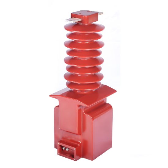
The ZZW-35 is a medium-voltage, cast-resin insulated current transformer (CT) engineered for precise current measurement and reliable protective relay operation in 11kV (IEC-rated) or 10kV (domestic system equivalent) power distribution networks. As a critical interface between primary high-current circuits and secondary instrumentation or protection systems, the ZZW-35 ensures galvanic isolation while accurately scaling down primary currents to standardized secondary values—typically 1A or 5A—for safe and accurate monitoring.
Operating Principle of Cast-Resin Insulation
Cast-resin insulation in the ZZW-35 employs vacuum pressure impregnation (VPI) technology using cycloaliphatic epoxy resin systems. This process eliminates air voids and moisture ingress by fully encapsulating the primary conductor, secondary windings, and magnetic core under controlled vacuum and pressure cycles. The resulting monolithic structure provides superior dielectric strength (≥30 kV/mm), excellent tracking resistance (CTI ≥600 V), and long-term hydrophobicity. Unlike oil-filled alternatives, the solid epoxy matrix prevents leakage, eliminates fire hazards, and maintains mechanical integrity across thermal cycling from –40°C to +105°C. The resin’s coefficient of thermal expansion closely matches that of copper and silicon steel, minimizing internal stresses during load transients.
Advantages Over Oil-Immersed Designs
Compared to traditional oil-immersed CTs, the ZZW-35’s cast-resin construction offers significant operational and safety benefits. It is inherently maintenance-free—no oil sampling, degassing, or level checks are required. The absence of flammable fluids makes it suitable for indoor substations, urban switchgear rooms, and confined industrial environments where fire codes restrict oil-filled equipment. Additionally, the compact footprint (typical height: 380 mm, diameter: 180 mm) enables space-efficient integration into ring main units (RMUs) and metal-clad switchgear. Environmental resilience is enhanced through UV-stable resin formulations that withstand outdoor exposure without cracking or chalking, even in coastal or high-pollution zones (pollution degree III per IEC 60664).
Typical Application Overview
The ZZW-35 is deployed across utility substations, industrial plants, renewable energy interconnection points, and commercial complexes requiring accurate revenue metering or fault detection. Its dual-purpose design supports both metering (accuracy classes 0.2S, 0.5S) and protection (classes 5P10, 5P20) functions within a single unit, reducing inventory complexity. In smart grid applications, it interfaces seamlessly with digital relays, SCADA systems, and IoT-enabled metering terminals. The transformer’s robust short-time thermal withstand capability (e.g., 20 kA for 1 s) ensures survival during downstream faults, maintaining system integrity until protective devices operate.
Technical Specifications
The ZZW-35 adheres to strict dimensional, electrical, and environmental parameters defined by IEC 61869-2 and GB/T 20840.2. Below is a representative specification table for standard configurations:
| Parameter | Value |
|---|---|
| Rated Voltage (Ur) | 11 kV (IEC) / 10 kV (GB) |
| Insulation Level (LI/AC) | 75 kV / 28 kV |
| Primary Current (Ip) | 50–3150 A (standard ratios) |
| Secondary Current (Is) | 1 A or 5 A |
| Accuracy Class (Metering) | 0.2S, 0.5S |
| Accuracy Class (Protection) | 5P10, 5P20 |
| Rated Output (Burden) | 5–30 VA (metering), 10–50 VA (protection) |
| Short-Time Thermal Withstand | 20 kA for 1 s (or 25 kA for 3 s optional) |
| Dynamic Withstand Current | 50 kA peak |
| Ambient Temperature Range | –40°C to +40°C (max. 24-h avg: +35°C) |
| Altitude Limit | ≤1000 m (derating above 1000 m per IEC 60071) |
| Relative Humidity | ≤95% non-condensing |
| Core Material | Grain-Oriented Electrical Steel (GOES), M4 grade |
| Insulation System | VPI cycloaliphatic epoxy resin, UL 94 V-0 rated |
Standard Service Conditions
The ZZW-35 is rated for continuous operation under IEC 60038 standard service conditions. Ambient temperature must not exceed +40°C, with a 24-hour average ≤+35°C and annual average ≤+20°C. Relative humidity may reach 95% provided condensation does not occur on surfaces. Installation altitude is limited to 1000 meters above sea level; for sites between 1000–2000 m, the power frequency withstand voltage must be reduced by 1% per 100 m increment. In tropical climates (IEC 60721-2-1), the resin formulation includes anti-fungal additives to prevent biological degradation. The transformer is designed for vertical or horizontal mounting on busbars or support insulators, with torque specifications for M12 primary terminals set at 35 N·m ±5%.
Electrical Performance Tolerances
Current error and phase displacement comply strictly with IEC 61869-2 Table 3 limits. For a 0.2S class unit at 100% rated current, current error must be within ±0.2%, and phase displacement ≤±10 minutes. At 20% load, error tolerance tightens to ±0.35%. Protection-class CTs (5P20) must maintain composite error ≤5% when subjected to 20× rated current with rated burden connected. Burden tolerance is ±10% of nominal VA rating. Saturation voltage (Vk) for 5P20 cores typically exceeds 200 V at 5 A secondary, ensuring adequate margin for modern numerical relays requiring high excitation impedance.
Typical Applications
The ZZW-35 serves as a foundational component in diverse power infrastructure scenarios where reliability, accuracy, and compliance are non-negotiable.
Substation Secondary Metering
In 11kV/0.4kV distribution substations, the ZZW-35 provides revenue-grade current signals to kWh meters, demand recorders, and power quality analyzers. Its 0.2S accuracy class ensures billing precision even at low loads (down to 1% of rated current), critical for utilities implementing time-of-use tariffs. The transformer’s low phase error minimizes reactive power measurement inaccuracies, supporting power factor correction schemes. Integration with AMI (Advanced Metering Infrastructure) systems is facilitated by stable ratio characteristics over decades of service, eliminating recalibration needs.
Industrial Power Distribution
Within manufacturing facilities, data centers, and mining operations, the ZZW-35 monitors feeder loads and enables selective coordination of circuit breakers. Its 5P20 protection class ensures accurate fault current replication during short circuits, allowing upstream relays to discriminate between local and remote faults. In arc-flash mitigation systems, the CT’s fast response (<10 ms rise time) triggers zone-selective interlocking within milliseconds. The cast-resin body resists chemical vapors (e.g., chlorine, ammonia) common in industrial atmospheres, preventing insulation degradation.
Renewable Energy Integration
At solar PV and wind farm collection substations, the ZZW-35 interfaces with protection relays that detect islanding, reverse power flow, or ground faults. Its symmetrical core design minimizes remanence after DC-offset fault currents—a frequent occurrence in inverter-based resources—ensuring rapid reset for subsequent events. The transformer’s wide dynamic range accommodates both normal generation currents and transient overcurrents during grid reconnection, supporting grid-code compliance (e.g., IEEE 1547, ENTSO-E).
Rural and Suburban Distribution Networks
In pole-mounted or pad-mounted transformers serving residential areas, the ZZW-35 enables load profiling and theft detection. Its compact size allows retrofit into legacy switchgear without structural modifications. Outdoor versions feature hydrophobic sheds that shed rain and resist pollution flashover, critical in agricultural regions with high dust or salt contamination. The 25–30 year service life reduces lifecycle costs in remote locations where access is difficult.
Compliance with International Standards
The ZZW-35 is certified to both global and Chinese national standards, ensuring interoperability across international supply chains.
IEC 61869-2 Certification Details
IEC 61869-2 governs instrument transformers for frequencies 15 Hz to 100 Hz. The ZZW-35 undergoes type tests including temperature rise (≤60 K for windings), short-circuit withstand (per IEC 61869-1 Annex B), and impulse voltage (75 kV peak, 1.2/50 µs waveform). Partial discharge levels are verified at ≤10 pC at 1.2 Um/√3, well below the 50 pC limit. Accuracy verification follows IEC 61869-2 Clause 7, with tests conducted at 5%, 20%, 100%, and 120% of rated current. Each production batch receives routine tests per Clause 8, including power frequency withstand (28 kV rms for 1 min) and winding continuity checks.
Alignment with GB/T 20840.2
GB/T 20840.2 mirrors IEC 61869-2 but includes supplementary requirements for Chinese grid operators. Notably, GB mandates a higher short-time thermal withstand (25 kA/3 s minimum for 10kV systems) and stricter partial discharge limits (≤5 pC). The ZZW-35’s domestic variant incorporates reinforced core clamping and thicker secondary insulation to meet these criteria. Additionally, GB requires flame retardancy testing per GB/T 5169.16 (equivalent to IEC 60695-11-10), which the cycloaliphatic resin satisfies with self-extinguishing properties.
Key Differences Between IEC and GB Standards
While harmonized in principle, practical differences exist. IEC uses 11kV as the standard system voltage, whereas GB specifies 10kV—though insulation levels remain identical (75/28 kV). GB also enforces mandatory third-party certification by CQC (China Quality Certification Centre), including factory audits. Environmental testing under GB includes salt fog exposure (96 h per GB/T 2423.17), absent in IEC base standards. Despite these variances, the ZZW-35 platform achieves dual compliance through modular design adjustments without compromising core performance.
On-Site Testing Procedures
Post-installation verification ensures the ZZW-35 performs within specified tolerances before energization.
Insulation Resistance Test
Using a 2500 V DC megohmmeter, measure insulation resistance between primary-to-secondary, primary-to-ground, and secondary-to-ground. Acceptance criteria: ≥1000 MΩ at 20°C. Correct for temperature using RT2 = RT1 × 2(T1–T2)/10. Values below 500 MΩ indicate moisture ingress or resin cracking and require investigation. Perform before and after power frequency withstand tests to detect insulation damage.
Turns Ratio Test
Apply a low-voltage AC source (5–10 V) to the primary and measure secondary voltage. Calculate actual ratio as Vp/Vs. Compare to nameplate ratio; tolerance must be within ±0.2% for metering class, ±0.5% for protection class. Use a dedicated turns ratio tester (e.g., Omicron CT Analyzer) for automated comparison against factory test reports. Deviations >1% suggest winding shorts or incorrect tap selection.
Polarity Test
Verify reducing polarity using the DC kick method: connect a 6–12 V battery momentarily across primary terminals (P1 to P2). Observe secondary voltage polarity with a center-zero galvanometer connected to S1–S2. A momentary positive deflection confirms correct polarity. Incorrect polarity causes 180° phase shift, leading to relay misoperation or meter reversal. Document results with timestamped oscillograms for audit trails.
Power Frequency Withstand Voltage Test
Apply 28 kV rms at 50 Hz between primary and grounded secondary/enclosure for 60 seconds. Use a calibrated test transformer with overcurrent trip set at 1.5× expected capacitive current (typically 5–10 mA). No flashover or disruptive discharge is permitted. Gradually ramp voltage at 1 kV/s to avoid transient overstress. This test validates insulation integrity after transport and installation stresses.
Short-Circuit Test (for CT)
For protection-class verification, inject 20× rated secondary current (e.g., 100 A for 5 A CT) into the secondary winding with rated burden connected. Measure voltage across burden; calculate composite error as [(Ip – n·Is)/Ip] × 100%. Must be ≤5% for 5P20 class. This confirms adequate core cross-section and low reluctance path under saturation conditions.
Preventive Maintenance Guide
Although cast-resin CTs are largely maintenance-free, periodic checks extend service life and prevent unexpected failures.
Annual Visual and Electrical Inspection
Inspect for surface cracks, tracking marks, or discoloration indicating thermal stress. Clean sheds with deionized water if contaminated. Torque-check primary and secondary terminals to 35 N·m and 2.5 N·m respectively. Re-measure insulation resistance and compare to baseline; a 50% drop warrants further diagnostics. Verify secondary circuit continuity and grounding integrity—open circuits can induce dangerous overvoltages.
Five-Year Comprehensive Maintenance
Every 60 months, perform partial discharge mapping using ultra-high-frequency (UHF) sensors. Acceptable PD magnitude remains ≤10 pC. Conduct excitation characteristic tests to detect core degradation: plot Vsec vs. Iexc; knee-point voltage should match factory data within ±5%. Replace secondary terminal blocks if oxidation exceeds 0.1 mm depth. Update asset management records with new test data for predictive analytics.
Maintenance Intervals and Fault Diagnosis
| Interval | Action | Fault Indicator |
|---|---|---|
| Annually | Visual inspection, IR scan, insulation resistance | Cracks, hot spots >10°C above ambient |
| 5 Years | PD test, excitation curve, terminal refurbishment | Knee-point shift >5%, PD >20 pC |
| After Fault | Ratio test, polarity check, withstand test | Ratio error >1%, insulation failure |
Common failure modes include secondary open-circuit (causing core saturation and overheating), moisture-induced surface tracking, and mechanical damage from busbar movement. Immediate replacement is required if insulation resistance falls below 100 MΩ or visible arcing marks appear.
Conclusion
The ZZW-35 11kV cast-resin current transformer represents a benchmark in medium-voltage instrumentation, combining IEC 61869-2 and GB/T 20840.2 compliance with field-proven reliability. Its VPI epoxy resin insulation eliminates fire risks and maintenance burdens associated with oil-filled designs, while the GOES silicon steel core ensures metrological stability across decades of service. Engineered for both metering (0.2S/0.5S) and protection (5P10/5P20) roles, it delivers precise current replication even under severe fault conditions—critical for modern digital substations and smart grids. With a rated thermal life exceeding 30 years under standard loading, the ZZW-35 minimizes total cost of ownership while meeting stringent safety and accuracy demands. Its adaptability to indoor/outdoor environments, compatibility with global grid codes, and rigorous type-testing protocol make it an optimal choice for utilities and industrial operators seeking future-proof instrumentation. As power systems evolve toward greater decentralization and digitization, the ZZW-35’s robust design ensures seamless integration into next-generation protection and metering architectures.