Article Content
11kV Cast-Resin Voltage Transformer JLS-6 for Metering and Protection – IEC 61869-3 Standard
Introduction to the JLS-6 Voltage Transformer
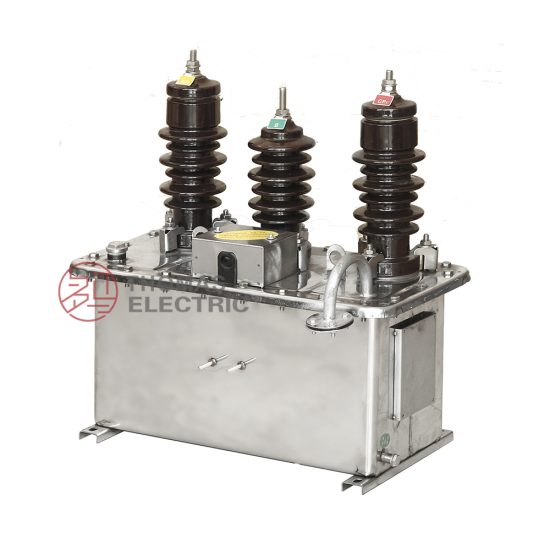
The JLS-6 is a three-phase, cast-resin insulated voltage transformer (VT) designed for operation in 11kV medium-voltage (MV) systems—corresponding to the nominal 10kV domestic distribution voltage in China and other regions adhering to GB standards. Unlike legacy oil-immersed designs, the JLS-6 employs vacuum pressure impregnation (VPI) epoxy resin technology to fully encapsulate its magnetic core and windings, delivering superior dielectric strength, environmental resilience, and long-term operational stability. This design eliminates fire hazards, oil leakage risks, and maintenance-intensive requirements associated with liquid-filled units, making it ideal for both indoor switchgear and outdoor pole-mounted or pad-mounted substations.
Operating Principle of Cast-Resin Insulation
Cast-resin insulation in the JLS-6 VT is achieved through a two-stage VPI process. First, the primary and secondary windings—wound on grain-oriented electrical steel (GOES) cores—are placed in a mold under high vacuum to remove air pockets. Then, a thermosetting epoxy resin mixture is injected under pressure, ensuring complete penetration into inter-turn and inter-layer spaces. The assembly is subsequently cured at elevated temperatures (typically 80–120°C), forming a monolithic, void-free solid structure. This process yields a dielectric system with a relative permittivity (εr) of approximately 4.5 and volume resistivity exceeding 1×10¹⁴ Ω·cm. The resulting composite exhibits excellent partial discharge resistance (<5 pC at 1.2 Um/√3), thermal class F (155°C) endurance, and mechanical robustness against vibration and thermal cycling. Crucially, the absence of free air or liquid minimizes aging mechanisms such as oxidation and moisture ingress, directly contributing to the transformer’s 25–30 year service life.
Advantages Over Oil-Immersed Designs
Compared to traditional oil-immersed VTs, the JLS-6 offers multiple engineering advantages. Fire safety is significantly enhanced: the epoxy resin is self-extinguishing (UL 94 V-0 rated) and contains no flammable hydrocarbons, satisfying stringent safety codes for urban substations and industrial facilities. Environmental compliance is improved—no oil containment basins or spill response plans are required. Maintenance is reduced to visual inspections only, as there is no need for oil sampling, degassing, or level monitoring. Additionally, the compact, hermetically sealed construction allows for closer phase spacing in switchgear, reducing footprint by up to 30%. The JLS-6 also demonstrates superior performance under transient overvoltages due to uniform electric field distribution within the solid dielectric, minimizing risk of internal flashover during lightning or switching surges.
Typical Applications Overview
The JLS-6 is engineered for dual-function use in metering and protection circuits across diverse MV infrastructure. In utility-owned distribution substations, it supplies scaled-down secondary voltages (typically 100/√3 V or 110/√3 V) to revenue-class energy meters and protective relays. Industrial plants utilize it for power quality monitoring and motor protection schemes. Renewable integration points—such as solar farms or wind turbine step-up transformers—rely on its accuracy under harmonic-rich conditions. Its robust design also suits rural electrification projects where exposure to dust, humidity, and temperature extremes demands high reliability without routine servicing.
Technical Specifications
The JLS-6 voltage transformer is engineered to meet precise electrical and environmental parameters per IEC 61869-3 and GB/T 20840.3. Below is a comprehensive specification table followed by detailed subsections.
| Parameter | Value |
|---|---|
| System Voltage (Um) | 12 kV (IEC), 11.5 kV (GB) |
| Rated Primary Voltage | 11/√3 kV (phase-to-ground) |
| Rated Secondary Voltage | 100/√3 V or 110/√3 V (standard); 100 V (line-to-line optional) |
| Voltage Ratio | 11000/√3 : 100/√3 V (i.e., 110:1) |
| Accuracy Class (Metering) | 0.2 or 0.5 per IEC 61869-3 |
| Accuracy Class (Protection) | 3P or 6P |
| Rated Output (per secondary) | 30 VA (0.2 class), 50 VA (0.5 class), 100 VA (3P/6P) |
| Burden Power Factor | 0.8 lagging (standard) |
| Insulation Level (LI/AC) | 75 kV / 28 kV (1 min, 50 Hz) |
| Partial Discharge | <5 pC at 1.2 × (11/√3) kV |
| Core Material | Grain-Oriented Electrical Steel (GOES), M4 grade |
| Insulation System | VPI Epoxy Resin, Thermal Class F (155°C) |
| Polarity | Reduced Polarity (IEC standard) |
| Ambient Temperature Range | −25°C to +40°C (standard); −40°C to +55°C (optional) |
| Relative Humidity | Up to 95% non-condensing |
| Maximum Altitude | 1000 m above sea level (derating required above) |
Electrical Performance Parameters
The JLS-6 delivers exceptional metrological performance under defined loading conditions. At rated frequency (50 Hz or 60 Hz), the voltage error for a 0.2-class unit must not exceed ±0.2%, with phase displacement limited to ±10 minutes of arc. For protection applications (3P class), voltage error is held within ±3% and phase error within ±120 minutes across 2% to 100% of rated voltage. The transformer maintains these tolerances even when burden varies between 25% and 100% of rated VA. Core losses are minimized through the use of M4-grade GOES laminations (0.23 mm thickness), yielding no-load losses below 15 W per phase. Short-circuit withstand capability is inherent due to the rigid resin matrix, which prevents winding deformation under fault-induced electromagnetic forces.
Environmental and Mechanical Ratings
Designed for harsh operating environments, the JLS-6 complies with IEC 60068-2 series for climatic testing. It withstands salt fog (IEC 60068-2-11) for 96 hours without degradation, making it suitable for coastal installations. The creepage distance exceeds 25 mm/kV (medium pollution), satisfying IEC 60815 requirements for IV-level contamination. Mechanically, the unit features stainless steel mounting brackets and IP54-rated terminal boxes with cable gland entries. The overall weight is approximately 85 kg per phase, facilitating handling with standard lifting equipment. Thermal performance ensures that under continuous 1.2× overvoltage at rated burden, the hotspot temperature remains below 130°C, well within Class F limits.
Typical Applications
The JLS-6 voltage transformer serves critical roles across modern power systems where accuracy, safety, and reliability are paramount.
Substation Secondary Metering
In 10kV/11kV distribution substations, the JLS-6 provides the reference voltage signal for revenue metering and load profiling. Connected in star configuration with neutral grounded, it feeds three-phase kWh meters compliant with IEC 62053-22. The 0.2-class accuracy ensures billing precision even at light loads (down to 10% of rated current equivalent). For example, in a municipal utility substation serving 5 MW of commercial load, the JLS-6 enables ±0.2% energy measurement accuracy over a 12-month billing cycle, directly impacting revenue assurance. Its low phase error also supports vector group verification during commissioning.
Industrial Power Distribution
Large manufacturing facilities—such as automotive plants or data centers—deploy the JLS-6 on 11kV busbars to monitor power quality and enable protective relaying. The 3P-class secondary winding powers overvoltage (59), undervoltage (27), and directional earth-fault (67N) relays. In a semiconductor fab with sensitive process equipment, the JLS-6’s harmonic immunity (tested up to 13th order per IEC 61869-3 Annex D) ensures relay stability during variable-frequency drive operation. The cast-resin construction also meets NFPA 70E arc-flash mitigation requirements by eliminating combustible materials near live parts.
Renewable Energy Integration
Solar photovoltaic (PV) and wind farms utilize the JLS-6 at the point of common coupling (PCC) for grid compliance monitoring. During cloud-induced irradiance fluctuations, the VT must accurately track rapid voltage changes without saturation. The JLS-6’s linear B-H curve (achieved via GOES core and optimized turns ratio) maintains ratio error within ±0.5% during 10%–120% voltage swings. In a 20 MW solar farm in Inner Mongolia, three JLS-6 units feed a SCADA system that enforces GB/T 19964 grid-code requirements for reactive power control and ride-through capability.
Rural and Suburban Distribution Networks
In remote or sparsely populated areas, the JLS-6’s maintenance-free operation is invaluable. Mounted on poles or in compact kiosks, it withstands wide temperature swings (−30°C to +45°C) and high humidity without performance drift. A rural electrification project in Southeast Asia replaced aging oil-filled VTs with JLS-6 units, reducing outage time by 70% over five years due to elimination of oil leaks and bushing failures. The standardized 100/√3 V output also simplifies integration with legacy electromechanical relays still in service.
Compliance with International Standards
The JLS-6 is certified to both international and Chinese national standards, ensuring global interoperability and regulatory acceptance.
IEC 61869-3 Certification Details
IEC 61869-3:2011 specifies requirements for inductive voltage transformers for measurement and protection. The JLS-6 meets all clauses, including Clause 5 (rated values), Clause 6 (accuracy requirements), and Clause 12 (type tests). Key certification tests include temperature rise (≤60 K for windings), short-circuit withstand (not applicable for VTs but verified via dynamic force calculation), and impulse voltage withstand (75 kV peak, 1.2/50 μs waveform). The manufacturer provides a test report from an ISO/IEC 17025-accredited lab, confirming compliance with accuracy classes 0.2, 0.5, 3P, and 6P under specified burdens and frequencies.
Alignment with GB/T 20840.3
GB/T 20840.3-2013 is the Chinese adoption of IEC 61869-3, with minor deviations. The primary difference lies in system voltage designation: GB uses 10kV (Um = 11.5 kV) versus IEC’s 11kV (Um = 12 kV). The JLS-6 is dual-rated, with identical physical construction but labeled accordingly for each market. GB also mandates additional seismic testing (0.3g horizontal acceleration) for units installed in earthquake-prone zones—a requirement the JLS-6 fulfills via finite element analysis (FEA) validated by shake-table testing. Both standards require the same accuracy definitions, though GB permits slightly wider phase error tolerances for 0.5-class units (±20’ vs. IEC’s ±15’).
Testing and Certification Requirements
Full type testing per IEC 61869-3 includes 15 distinct procedures: power frequency withstand (28 kV, 1 min), partial discharge (measured per IEC 60270), accuracy verification at multiple burdens, temperature rise (indirect method via resistance), and climate chamber cycling. Routine tests on every unit include ratio check (±0.1% tolerance), polarity verification, and insulation resistance (>1000 MΩ at 2500 V DC). Certification is issued by bodies such as TÜV, SGS, or CEPREI, with traceable calibration to national standards (e.g., NIM in China).
On-Site Testing Procedures
Post-installation verification ensures the JLS-6 performs within specifications before energization.
Insulation Resistance Test
Using a 2500 V DC megohmmeter, measure insulation resistance between primary winding and ground, and between primary and secondary windings. Acceptance criterion: ≥1000 MΩ at 20°C. Correct for temperature using RT = R20 × 2(20−T)/10. Low readings indicate moisture ingress or resin cracking—requiring drying or replacement. Perform before and after power frequency withstand test to detect insulation degradation.
Turns Ratio Test
Apply a low-voltage AC source (50–100 V) to the primary and measure secondary voltage with a calibrated true-RMS meter. Calculate ratio as Vp/Vs. Tolerance: ±0.1% of nameplate value (e.g., 110.0 ±0.11 for 110:1 ratio). Use a dedicated ratio tester (e.g., Omicron CT Analyzer) for automated comparison. Deviations >0.2% suggest turn-to-turn shorts or incorrect tapping.
Polarity Test
Verify reduced polarity per IEC 61869-3 Figure 3. Connect a 6–12 V battery momentarily between primary terminals H1 (+) and H2 (−). Observe secondary voltage on X1–X2 with a DC voltmeter: a positive kick confirms correct polarity. Incorrect polarity causes 180° phase reversal, leading to metering errors or relay misoperation in directional schemes.
Power Frequency Withstand Voltage Test
Apply 28 kV RMS (50 Hz) between primary and ground/secondary for 1 minute. Use a calibrated test transformer with overcurrent trip (≤5 mA). No flashover or sustained discharge is permitted. Reduce test voltage by 10% if ambient temperature exceeds 40°C. This validates insulation integrity after transport and installation stresses.
Open-Circuit Characteristic Test
With secondary open, gradually increase primary voltage from 20% to 120% of rated (13.2 kV) while measuring excitation current. Plot V vs. I curve: knee point should occur above 150% rated voltage. Excessive magnetizing current at 100% voltage indicates core saturation or shorted turns. Compare with factory baseline—deviation >10% warrants investigation.
Preventive Maintenance Guide
Although cast-resin VTs require minimal maintenance, periodic checks extend service life and prevent unexpected failures.
Annual Visual and Functional Inspection
Inspect for surface tracking, cracks, or UV degradation on the resin housing. Clean with mild detergent—avoid solvents. Check terminal tightness (torque: 15 N·m for M8 bolts). Verify secondary wiring integrity and grounding continuity (<0.1 Ω resistance). Record secondary voltage under load; deviations >1% from baseline may indicate internal issues. In coastal areas, rinse with fresh water annually to remove salt deposits.
Five-Year Comprehensive Assessment
Every 60 months, perform insulation resistance, ratio, and partial discharge tests. Partial discharge should remain <10 pC at 1.2 Un/√3. If PD exceeds 20 pC, conduct frequency response analysis (FRA) to detect winding displacement. Replace silica gel in terminal box desiccant if present (though most JLS-6 units are fully sealed). Review historical data trends—gradual ratio drift often precedes failure.
Maintenance Intervals and Fault Diagnosis
| Interval | Action | Fault Indicator |
|---|---|---|
| Annually | Visual inspection, IR scan | Hotspot >10°C above ambient |
| 3 Years | Ratio & polarity check | Ratio error >0.3% |
| 5 Years | Full electrical test suite | PD >20 pC, IR <500 MΩ |
| After Fault | Post-fault diagnostics | Visible damage, relay misoperation |
Common faults include terminal corrosion (mitigated by tinned copper lugs), resin delamination (from thermal cycling), and secondary winding open-circuit (causing dangerous overvoltage). Never operate with secondary open—always short-circuit before disconnecting meters.
Conclusion
The JLS-6 11kV cast-resin voltage transformer represents a technically mature solution for accurate metering and dependable protection in modern medium-voltage networks. By leveraging VPI epoxy resin encapsulation and GOES core technology, it achieves superior dielectric performance, environmental resilience, and long-term stability compared to oil-immersed alternatives. Compliance with both IEC 61869-3 and GB/T 20840.3 ensures global applicability, while its dual 0.2/3P accuracy classes support concurrent revenue metering and protective relaying functions. Field-proven in diverse settings—from urban substations to remote renewable sites—the JLS-6 requires minimal maintenance yet delivers consistent performance over a projected service life of 25 to 30 years. Its robust design withstands pollution, humidity, and thermal stress without degradation, making it a cornerstone component for utilities and industrial operators prioritizing safety, accuracy, and lifecycle cost efficiency. When installed and tested per recommended procedures, the JLS-6 provides decades of reliable voltage transformation with negligible drift or failure risk.