Article Content
Introduction
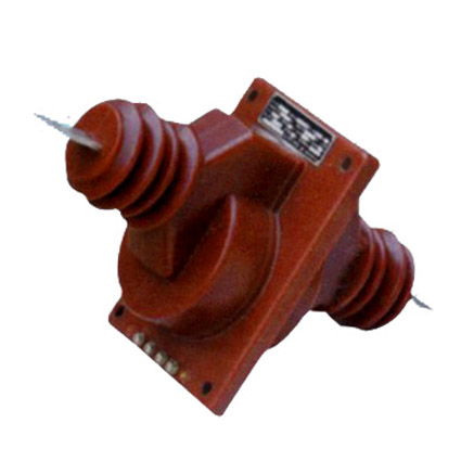
The LA-10Q current transformer is a critical component in medium-voltage power systems, specifically engineered for reliable and accurate current measurement and protection in 10 kV networks. Designed to meet stringent international standards such as IEC 61869 and GB/T 20840, the LA-10Q ensures high performance under demanding electrical and environmental conditions. Its robust epoxy resin encapsulation provides excellent insulation, mechanical strength, and resistance to moisture, dust, and partial discharge—making it ideal for both indoor switchgear and outdoor installations. Current transformers like the LA-10Q play a pivotal role in enabling protective relays, energy meters, and monitoring systems to function accurately by stepping down high primary currents to standardized, manageable secondary levels (typically 1 A or 5 A). Selecting the appropriate LA-10Q variant requires careful consideration of system parameters including voltage class, transformation ratio, accuracy requirements, burden compatibility, and installation environment. This selection guide aims to provide engineers and system designers with clear, actionable criteria to ensure optimal performance, safety, and compliance when integrating the LA-10Q into 10 kV distribution or transmission infrastructure.
System Voltage
The LA-10Q current transformer is explicitly rated for use in systems with a nominal voltage of 10 kV. However, proper selection demands a thorough understanding of not just the nominal voltage but also the system’s maximum operating voltage, insulation coordination, and overvoltage conditions. The transformer’s insulation system must withstand both continuous operating voltages and transient surges without breakdown or degradation. According to IEC standards, a 10 kV class device typically corresponds to a highest system voltage for equipment (Um) of 12 kV. This margin accommodates normal voltage fluctuations and temporary overvoltages that may occur during switching operations or faults.
Key voltage-related specifications for the LA-10Q include:
- Rated Primary Voltage (Up): 10 kV
- Highest Voltage for Equipment (Um): 12 kV
- Power Frequency Withstand Voltage: 42 kV (1 min)
- Lightning Impulse Withstand Voltage: 75 kV (1.2/50 µs wave)
These values ensure the LA-10Q maintains dielectric integrity under standard test conditions. Installers must verify that the local grid’s actual operating voltage—including any planned future upgrades—falls within these limits. Using the LA-10Q on systems exceeding 12 kV Um compromises safety and violates certification requirements. Additionally, the transformer’s creepage distance and pollution degree rating (typically suitable for pollution degree III environments) must align with the installation site’s contamination level (e.g., coastal, industrial, or rural areas).
| Voltage Parameter | Symbol | Value | Standard Reference |
|---|---|---|---|
| Rated System Voltage | Un | 10 kV | IEC 60038 |
| Highest Voltage for Equipment | Um | 12 kV | IEC 60071-1 |
| Power Frequency Withstand Voltage | Ud | 42 kV / 1 min | IEC 61869-3 |
| Lightning Impulse Withstand Voltage | Up | 75 kV peak | IEC 60060-1 |
Transformation Ratio
The transformation ratio of a current transformer defines the relationship between the primary current (Ip) and the secondary current (Is). For the LA-10Q, this ratio is expressed as Ip:Is, where Is is typically standardized at either 1 A or 5 A. Selecting the correct ratio is essential for ensuring that connected instruments and protective devices operate within their optimal range while maintaining safety and accuracy.
Common transformation ratios available for the LA-10Q include 50/1, 75/1, 100/1, 150/1, 200/1, 300/1, 400/1, 600/1, and their 5 A equivalents (e.g., 100/5, 200/5, etc.). The choice depends on the expected load current and fault current levels in the circuit. For instance, a feeder carrying a normal load of 180 A might use a 200/1 or 200/5 ratio to allow headroom for overload conditions while keeping the secondary current proportional and within metering ranges.
When determining the appropriate ratio, engineers must consider:
- Normal Load Current: The CT should operate near 60–80% of its rated primary current under typical conditions to maximize accuracy.
- Maximum Fault Current: The CT must not saturate during short-circuit events; thus, the ratio should be selected so that even high fault currents remain within the instrument security factor (FS) or accuracy limit factor (ALF) limits.
- Secondary Device Requirements: Meters and relays specify minimum and maximum input currents. A 5 A system may be preferred for electromechanical relays, while modern digital relays often perform better with 1 A inputs due to lower burden and reduced copper losses.
Multi-ratio versions of the LA-10Q are also available, featuring multiple secondary windings or tap points on a single core (e.g., 400/200/100/1 A). These offer flexibility for future load changes or dual applications (e.g., one ratio for metering, another for protection). However, unused taps must be short-circuited to prevent dangerous open-circuit conditions.
It is crucial to avoid selecting an excessively high ratio (e.g., 600/1 for a 50 A load), as this leads to poor resolution at low currents and degraded metering accuracy. Conversely, too low a ratio risks saturation during overloads or faults, potentially causing relay misoperation or measurement errors.
| Primary Current (A) | Secondary Current (A) | Typical Application | Notes |
|---|---|---|---|
| 50 – 150 | 1 or 5 | Light feeders, small transformers | Prefer 1 A for long cable runs |
| 200 – 400 | 1 or 5 | Main distribution circuits | 5 A common for legacy systems |
| 600 | 1 or 5 | Substation incomers, large motors | Verify ALF ≥ 10 for protection |
| Multi-tap (e.g., 400/200/100) | 1 | Flexible or evolving loads | Short unused taps! |
Accuracy Class
Accuracy class defines the permissible error limits of a current transformer under specified operating conditions. For the LA-10Q, accuracy classes are designated separately for metering (measurement) and protection applications, as each has distinct performance requirements. Metering CTs prioritize precision at low to nominal currents, while protection CTs must maintain linearity up to high multiples of rated current during fault conditions.
According to IEC 61869-2, common accuracy classes for the LA-10Q include:
- Metering Classes: 0.2, 0.5, 1.0 — indicating maximum composite error of ±0.2%, ±0.5%, or ±1.0% at rated current and specified burden.
- Protection Classes: 5P10, 5P20, 10P10, etc. — where “5P” means ≤5% composite error at the accuracy limit factor (e.g., 10× rated current), and “10P” allows ≤10% error.
For revenue metering or high-precision monitoring, Class 0.2 or 0.5 is typically mandated by utility regulations. General-purpose metering may accept Class 1.0. In protection applications, the required class depends on the relay type and fault current magnitude. For example, a 5P20 CT ensures the secondary current remains within 5% of the true value even when the primary current is 20 times the rated value—critical for time-overcurrent or differential relays.
Selecting the correct accuracy class involves matching the CT’s performance to the connected burden (expressed in volt-amperes, VA) and the operational current range. The LA-10Q’s accuracy is only guaranteed when used with burdens equal to or less than its rated burden (e.g., 10 VA, 15 VA, or 30 VA). Exceeding this burden increases errors and may invalidate the stated accuracy class.
Additionally, the concept of “Instrument Security Factor” (FS) applies to metering CTs—it limits the secondary current during overloads to protect connected meters. An FS ≤ 5 means the CT saturates before the secondary current exceeds 5× rated value, preventing meter damage. Protection CTs do not use FS; instead, they rely on ALF (Accuracy Limit Factor).
5. Burden Calculation
The burden of a current transformer (CT) is the total impedance presented to its secondary winding, comprising connected devices (relays, meters, leads) and wiring. Accurate burden calculation ensures CTs operate within accuracy class limits under normal and fault conditions.
Burden is typically expressed in volt-amperes (VA) at a standard current (usually 5 A or 1 A). The total burden \( Z_b \) is calculated as:
\[
Z_b = \frac{VA}{I_s^2}
\]
where \( I_s \) is the secondary current (e.g., 5 A).
Key components contributing to burden include:
- Relay/Meter Impedance: Provided by manufacturer datasheets.
- Lead Resistance: Depends on wire length, cross-section, and material (typically copper).
- Connection Resistance: Often negligible but included for precision.
| Component | Typical Impedance (Ω) | Notes |
|---|---|---|
| Digital Relay | 0.02 – 0.1 | Low burden; varies by model |
| Electromechanical Relay | 0.5 – 2.0 | Higher burden due to coil resistance |
| Meter (Analog) | 0.1 – 0.5 | Depends on movement type |
| Lead Wire (per 100 m, 4 mm² Cu) | 0.44 | Round-trip resistance: double one-way |
| Terminal Blocks/Connections | 0.01 – 0.05 | Usually minor but cumulative |
Example: For a 5 A system with 50 m of 4 mm² lead (round trip = 100 m), a digital relay (0.05 Ω), and connections (0.02 Ω):
Total \( R = 0.44 + 0.05 + 0.02 = 0.51\ \Omega \)
Burden \( VA = I_s^2 \times R = 25 \times 0.51 = 12.75\ \text{VA} \)
Designers must ensure the CT’s rated burden (e.g., 15 VA) exceeds the calculated burden to maintain accuracy. Overloading causes saturation and measurement errors.
6. Short-Circuit Performance
Current transformers must withstand high short-circuit currents without mechanical damage or loss of insulation integrity. During faults, primary currents can reach 20–100× nominal values, inducing large forces and thermal stress.
Two critical parameters define short-circuit performance:
- Thermal Withstand Capability: Expressed as \( I_{th}^2 t \), where \( I_{th} \) is the RMS short-circuit current (kA) and \( t \) is duration (s), typically 1–3 seconds.
- Dynamic (Electrodynamic) Withstand: Peak current (e.g., 2.5× \( I_{th} \)) that the CT can endure without deformation.
Standards such as IEC 61869-2 specify test requirements. CTs are tested at rated short-time current (e.g., 40 kA for 1 s) and peak withstand current (e.g., 100 kA).
| Parameter | Symbol | Typical Value | Standard Reference |
|---|---|---|---|
| Rated Short-Time Current | \( I_{th} \) | 20–63 kA | IEC 61869-2, IEEE C57.13 |
| Duration | \( t \) | 1 s, 3 s | System protection coordination |
| Peak Withstand Current | \( I_{pk} \) | 2.5 × \( I_{th} \) | Assumes X/R ≤ 15 |
| Thermal Limit | \( I^2t \) | e.g., (40 kA)² × 1 s = 1600 kA²s | Used for cable and equipment coordination |
During short circuits, CT cores may saturate, distorting secondary current. While this affects protection relay operation, the CT itself must remain physically intact. Proper mechanical bracing, robust winding construction, and adequate clearances prevent failure.
Designers should verify CT short-circuit ratings against the maximum prospective fault current at the installation point, obtained from system studies.
7. Environmental Considerations
Environmental factors significantly influence CT selection, longevity, and performance. These include temperature, humidity, altitude, pollution, and exposure to chemicals or UV radiation.
Ambient Temperature: Standard CTs operate between –5°C to +40°C. Extended ranges (e.g., –40°C to +55°C) require special materials and design. High temperatures accelerate insulation aging; low temperatures may embrittle plastics.
Altitude: Above 1000 m, air density decreases, reducing dielectric strength and cooling efficiency. CTs rated for high-altitude service often feature increased creepage distances and derated thermal capacity.
Pollution and Humidity: In coastal or industrial areas, salt spray or chemical contaminants necessitate CTs with higher pollution degree ratings (e.g., IP54 or IP65 enclosures) and hydrophobic coatings.
| Condition | Impact on CT | Mitigation Strategy |
|---|---|---|
| High Humidity / Condensation | Insulation degradation, tracking | Sealed enclosures, silica gel breathers, conformal coating |
| Industrial Pollution | Surface leakage, flashover | Increased creepage distance (>25 mm/kV), silicone housing |
| UV Exposure (Outdoor) | Material degradation (epoxy, polymers) | UV-stabilized resins, metal housings |
| Extreme Cold | Brittleness, oil solidification (oil-filled CTs) | Synthetic ester fluids, flexible composites |
| High Altitude (>1000 m) | Reduced cooling, lower dielectric strength | Derating (≈1% per 100 m above 1000 m), larger clearances |
Compliance with standards like IEC 60068 (environmental testing) and IEC 60529 (IP ratings) ensures reliability. For hazardous locations (e.g., oil & gas), explosion-proof certifications (ATEX, IECEx) may be required.
8. Installation and Verification Checklist
A systematic checklist ensures correct CT installation, safety, and performance validation. This reduces commissioning errors and enhances long-term reliability.
| # | Check Item | Status (✓/✗) | Remarks |
|---|---|---|---|
| 1 | CT ratio matches system requirements and relay settings | Verify primary/secondary current ratings | |
| 2 | Burden calculation ≤ CT rated burden | Include all devices and lead resistance | |
| 3 | Short-circuit rating ≥ system fault level | Confirm \( I_{th} \) and \( I_{pk} \) adequacy | |
| 4 | Secondary terminals properly shorted before disconnection | Prevents dangerous open-circuit voltage | |
| 5 | Polarity marked correctly (P1/P2, S1/S2) | Critical for differential and directional protection | |
| 6 | Grounding of CT case and one secondary terminal (per code) | Usually S2 grounded to avoid floating potentials | |
| 7 | Environmental rating suitable for location (IP, temp, etc.) | Check enclosure and material specs | |
| 8 | Insulation resistance > 100 MΩ (500 V DC test) | Per IEC 60270 or local standards | |
| 9 | Excitation curve test performed (for protection CTs) | Verifies knee-point and saturation margin | |
| 10 | Labeling legible and permanent (ratio, class, serial no.) | Required for maintenance and audits |
This checklist should be completed during pre-commissioning and documented. Any “✗” item requires corrective action before energization.