Article Content
High-Performance 11kV Cast-Resin Current Transformer LXK-120 for Metering & Protection per IEC 61869-2
Introduction to the LXK-120 Current Transformer
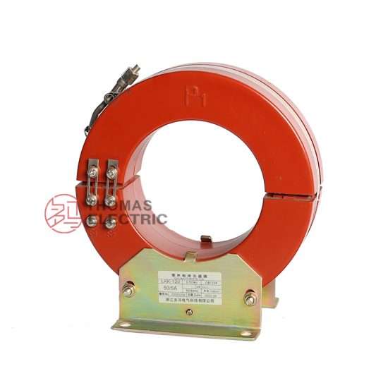
The LXK-120 is a ring-type, cast-resin insulated current transformer (CT) engineered for high-accuracy current measurement and reliable protective relaying in medium-voltage power systems rated at 11kV (IEC standard), corresponding to 10kV domestic system voltage. Its design leverages vacuum pressure impregnation (VPI) epoxy resin technology to encapsulate a grain-oriented electrical steel (GOES) core, secondary windings, and embedded terminals into a monolithic, void-free structure. This construction eliminates moisture ingress, suppresses partial discharges, and ensures long-term dielectric integrity under thermal and electrical stress.
Operating Principle of Cast-Resin Insulation
Cast-resin insulation in the LXK-120 employs a two-stage VPI process where dry-wound components are first evacuated to remove air, then impregnated under pressure with cycloaliphatic epoxy resin. The assembly is subsequently cured at elevated temperatures (typically 80–120°C) to form a rigid, thermoset composite. This method achieves a dielectric strength exceeding 20 kV/mm and a partial discharge inception voltage (PDIV) greater than 15 kV (peak). Unlike oil-filled alternatives, the solid resin matrix provides superior mechanical stability, eliminates fire hazards, and requires no maintenance related to fluid levels or degradation. The homogeneous structure also minimizes thermal gradients during load cycling, reducing mechanical fatigue on internal conductors.
Advantages Over Oil-Immersed Designs
Compared to traditional oil-immersed CTs, the LXK-120 offers significant operational and safety benefits. The absence of flammable insulating oil eliminates explosion risks in indoor substations and confined spaces, aligning with IEC 61439-2 requirements for arc-resistant switchgear. Its compact toroidal geometry reduces footprint by up to 40% versus equivalent oil units, facilitating retrofitting in space-constrained panels. Furthermore, cast-resin CTs exhibit negligible aging under normal service conditions—no oil sampling, drying, or replacement is needed over a 30-year lifespan. Environmental compliance is enhanced as the unit contains no PCBs or volatile organic compounds (VOCs), simplifying end-of-life disposal per RoHS and WEEE directives.
Typical Application Overview
The LXK-120 is deployed across utility substations, industrial plants, and renewable energy facilities where precision metering and dependable fault detection are critical. In 10/11kV distribution networks, it interfaces with revenue-class energy meters (Class 0.2S) and digital protective relays (e.g., overcurrent, earth-fault). Its dual-core configuration—one optimized for metering (0.2S/5P10), another for protection (5P20)—enables simultaneous high-accuracy billing and fast tripping during short circuits. Common installations include ring-main units (RMUs), metal-clad switchgear, and pad-mounted transformers, particularly in environments demanding low maintenance and high reliability, such as data centers, hospitals, and offshore platforms.
Technical Specifications
The LXK-120 adheres to stringent electrical and environmental parameters defined by IEC 61869-2 and GB/T 20840.2. Key specifications ensure compatibility with global medium-voltage infrastructure while supporting precise metrology and robust protection functions.
Electrical Ratings and Performance Parameters
The LXK-120 features a primary voltage rating of 11kV (IEC) / 10kV (domestic), with a highest system voltage (Um) of 12kV. Standard current ratios include 50/5, 75/5, 100/5, 150/5, 200/5, 300/5, 400/5, 600/5, and 800/5 A, customizable upon request. Accuracy classes are 0.2S for metering (per IEC 61869-2 Table 102) and 5P10 or 5P20 for protection. Rated burden is 15 VA (metering) and 30 VA (protection) at cos φ = 0.8 lagging. The instrument security factor (FS) is ≤5 for metering cores, ensuring saturation does not occur below 5× rated current. Thermal short-time withstand current is 20 kA for 1 second, with dynamic withstand of 50 kA peak. Insulation level complies with IEC 60071-1: 75 kV (1 min power frequency) and 95 kV (lightning impulse).
Environmental and Mechanical Specifications
Designed for both indoor and outdoor use, the LXK-120 operates within an ambient temperature range of –25°C to +40°C (extended to +55°C with derating). Relative humidity tolerance is ≤95% non-condensing. Altitude rating is up to 1,000 m above sea level; for installations between 1,000–3,000 m, voltage withstand values must be adjusted per IEC 60071-2 (approximately 1% reduction per 100 m). The housing is UV-stabilized cycloaliphatic epoxy with IP54 ingress protection when mounted vertically. Mounting is via M10 stainless steel bolts through a standardized flange (dimensions per IEC 61869-2 Annex C). Total weight is approximately 8.5 kg, with a window diameter of 120 mm to accommodate primary conductors up to 80 mm OD.
Core and Winding Construction Details
The magnetic circuit utilizes CRGO (cold-rolled grain-oriented) silicon steel laminations with a thickness of 0.3 mm and core loss ≤1.0 W/kg at 1.7 T, 50 Hz. Secondary windings are wound with oxygen-free copper (OFC) wire, insulated with Class F (155°C) enamel. Terminals are tinned copper studs rated for 600 V, marked per IEC 61869-2 polarity conventions (P1/P2 for primary, S1/S2 for secondary). The resin matrix incorporates silica fillers to match the coefficient of thermal expansion (CTE) of copper and steel, minimizing interfacial stresses during thermal cycling. Partial discharge levels are guaranteed <10 pC at 1.2 Um/√3 during factory testing.
Typical Applications
The LXK-120’s dual-core architecture and high accuracy make it suitable for diverse power system roles requiring both fiscal metering and protective coordination.
Substation Secondary Metering Systems
In 11kV/0.4kV distribution substations, the LXK-120 supplies current signals to Class 0.2S revenue meters for accurate energy billing. Its 0.2S class ensures error remains within ±0.2% from 20% to 120% of rated current and ±0.35% at 5% In, meeting EN 50470-1 and DLMS/COSEM requirements. The low phase displacement (<±10 minutes) prevents reactive energy errors in three-phase systems. Installed in ring-main units feeding commercial complexes or municipal grids, it enables precise load profiling and demand-side management without recalibration over decades.
Industrial Power Distribution Monitoring
Within manufacturing facilities, the LXK-120 monitors feeders supplying motors, transformers, and process equipment. The protection core (5P20) drives overcurrent relays that trip within 40 ms during faults, preventing equipment damage. Simultaneously, the metering core feeds power quality analyzers to track harmonics, unbalance, and efficiency metrics. In arc furnace or welding plant environments, its high saturation margin (20× In) avoids false tripping from transient inrush currents. Compatibility with Modbus RTU or IEC 61850-9-2 LE sampled values allows integration into SCADA systems for real-time diagnostics.
Renewable Energy Integration Points
At solar PV or wind farm collection points, the LXK-120 measures exported power to grid operators while protecting inverters and step-up transformers. Its wide dynamic range captures low nighttime loads (as low as 5% In) with 0.2S accuracy and handles fault currents during grid disturbances. Outdoor-rated versions withstand coastal salt spray (IEC 60068-2-52) and desert dust (IEC 60529), ensuring reliability in remote sites. The absence of oil prevents contamination risks near sensitive ecological zones, a key advantage over liquid-filled alternatives.
Rural and Suburban Distribution Networks
In rural electrification projects, the LXK-120 is mounted on pole-top transformers or underground RMUs to monitor single-phase or three-phase feeders. Its compact size simplifies installation in congested urban duct banks, while the 120 mm aperture accommodates bundled conductors. The 5P10 protection core coordinates with downstream fuses to isolate faults selectively, minimizing outage scope. With a 30-year service life and zero maintenance, it reduces lifecycle costs in regions with limited technical manpower. Compliance with GB/T 20840.2 ensures interoperability with Chinese-manufactured switchgear prevalent in emerging markets.
Compliance with International Standards
The LXK-120 is certified to IEC 61869-2:2012 (“Instrument transformers – Part 2: Additional requirements for current transformers”) and aligned with China’s GB/T 20840.2-2014, ensuring global acceptance and interoperability.
IEC 61869-2 Certification Requirements
IEC 61869-2 mandates rigorous type, routine, and special tests. Type tests include temperature rise (≤60 K for windings), short-circuit withstand (250× In for 1 s), and accuracy verification across burden ranges. Routine tests performed on every unit comprise power frequency withstand (75 kV, 1 min), partial discharge (<10 pC at 1.2 Um/√3), and turns ratio error (±0.1% for 0.2S class). Special tests like seismic qualification (IEC 60068-3-3) or chopped impulse withstand may be requested. Certification is issued by accredited labs (e.g., KEMA, CESI) with test reports traceable to SI units.
Alignment with GB/T 20840.2 Domestic Standard
GB/T 20840.2 mirrors IEC 61869-2 but includes localized requirements: altitude correction factors for installations >1,000 m, stricter pollution degree ratings (III vs. II), and mandatory lightning impulse tests at –30°C for northern climates. The LXK-120 meets all GB-specific clauses, including terminal marking in Chinese characters and compatibility with domestic relay burdens (e.g., DSY-type electromechanical relays). Notably, GB/T 20840.2 permits a slightly wider phase error tolerance (±15 minutes vs. ±10) for 0.2S class, which the LXK-120 exceeds due to its high-permeability core.
Key Differences Between IEC and Domestic Standards
While IEC 61869-2 focuses on performance under standard conditions, GB/T 20840.2 emphasizes environmental resilience for China’s diverse geography—from humid southern coasts to arid western plateaus. IEC allows synthetic ester fluids for hybrid designs, but GB prohibits non-mineral oils in 10kV CTs. Additionally, GB requires a 10% higher short-circuit withstand (22 kA vs. 20 kA) for urban networks with lower source impedance. The LXK-120’s design envelope accommodates both regimes, enabling dual-certification without hardware changes. Documentation includes bilingual (English/Chinese) test certificates and wiring diagrams per GB 4208.
On-Site Testing Procedures
Post-installation verification ensures the LXK-120 performs within specification before energization. All tests follow IEC 61869-2 Annex E and IEEE C57.13.2 guidelines.
Insulation Resistance Test
Using a 2,500 V DC megohmmeter, measure insulation resistance between primary-to-secondary, primary-to-ground, and secondary-to-ground. Acceptance criterion: ≥1,000 MΩ at 25°C. Correct for temperature using RT2 = RT1 × 2(T1–T2)/10. Low readings indicate moisture ingress or resin cracking—retest after 24-hour drying at 60°C. Never perform this test with secondary windings shorted, as it masks inter-turn faults.
Turns Ratio and Polarity Verification
Apply 1–5 V AC (50/60 Hz) to the secondary winding and measure induced primary voltage. Ratio error = [(Vp/Vs) – N] / N × 100%, where N is nominal ratio. Tolerance: ±0.1% for 0.2S class. For polarity, connect a 1.5 V battery between S1–S2; a momentary positive deflection on a DC voltmeter at P1–P2 confirms additive polarity (standard for IEC). Reversed polarity causes 180° phase shift, leading to metering errors or relay misoperation.
Power Frequency Withstand Voltage Test
Apply 28 kV RMS (40% of 75 kV type test value) at 50 Hz for 1 minute between primary and grounded secondary/housing. Use a calibrated HV test set with automatic trip at 10 mA leakage current. Failure indicates insulation breakdown—inspect for surface tracking or voids. This reduced test avoids stressing aged insulation while verifying integrity post-transport.
Secondary Winding Resistance Measurement
Measure DC resistance of each secondary winding with a 4-wire Kelvin bridge. Compare to factory baseline (±5% tolerance). A 10% increase suggests broken strands; a decrease indicates shorted turns. Temperature-correct to 75°C using R75 = Rt × (234.5 + 75)/(234.5 + t). Record values for future trending—resistance drift often precedes thermal failure.
Excitation (Saturation) Characteristic Test
Gradually apply AC voltage to the secondary while measuring current. Plot volts vs. amps to identify knee-point voltage (Vk). For 5P20 cores, Vk must exceed 20 × In × (Rct + Rb), where Rct is CT resistance and Rb is burden. A depressed knee-point indicates core degradation from mechanical shock or DC offset. This test is critical after nearby short circuits to verify protection reliability.
Preventive Maintenance Guide
Although cast-resin CTs require minimal upkeep, periodic checks extend service life and prevent unexpected failures.
Annual Visual and Electrical Inspection
Inspect for surface cracks, UV discoloration, or tracking marks on the resin housing. Clean with isopropyl alcohol if contaminated by dust or salt. Verify terminal tightness (torque: 12 N·m for M6 studs). Perform insulation resistance and secondary resistance tests annually. Compare results to baseline—if insulation drops >50% or resistance varies >10%, schedule diagnostic testing. Check grounding continuity (<0.1 Ω) between flange and switchgear frame to prevent capacitive coupling errors.
Five-Year Diagnostic Testing Schedule
Every five years, conduct full excitation characteristic and partial discharge mapping (if portable PD detector available). Partial discharge >20 pC at operating voltage warrants replacement. Re-measure ratio and polarity to detect winding deformation from electromagnetic forces. Update maintenance logs with thermal imaging data—hot spots >10 K above ambient on terminals indicate loose connections. After any system fault exceeding 10 kA, perform immediate post-event testing regardless of schedule.
Maintenance Intervals and Fault Diagnosis
| Interval | Task | Acceptance Criteria |
|---|---|---|
| Annual | Visual inspection, IR test, terminal torque check | No cracks; IR >1,000 MΩ; torque 12±1 N·m |
| 5 Years | Excitation curve, PD test, ratio verification | Vk ≥ spec; PD <20 pC; ratio error ≤±0.1% |
| Post-Fault | Full suite + thermal scan | No deviation from pre-fault baseline |
Common faults include open-circuited secondaries (causing dangerous overvoltages), core remanence from DC faults (shifting excitation curve), and terminal corrosion in coastal areas. Always short secondary terminals before disconnecting meters to prevent insulation damage.
Conclusion
The LXK-120 11kV cast-resin current transformer represents a benchmark in medium-voltage instrumentation, combining metrological precision with rugged protection capabilities. Its VPI epoxy resin encapsulation ensures decades of maintenance-free operation, while the GOES silicon steel core delivers exceptional linearity across the 5%–120% current range required for 0.2S accuracy. Full compliance with IEC 61869-2 and GB/T 20840.2 guarantees interoperability in global power systems, from European smart grids to Chinese rural networks. The dual-core design eliminates the need for separate metering and protection CTs, reducing capital expenditure and panel space. With a proven service life of 25–30 years under standard conditions—and immunity to fire, explosion, and environmental degradation—the LXK-120 offers unmatched lifecycle value. Its rigorous factory testing and straightforward field verification protocols further minimize commissioning risks, making it the preferred choice for engineers prioritizing accuracy, safety, and long-term reliability in 10/11kV applications.