Article Content
Introduction
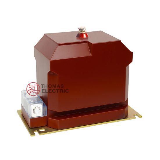
The REL-10 Voltage Transformer is a critical component in medium-voltage power systems, specifically engineered for reliable and accurate voltage measurement and protection at the 10 kV level. Designed in compliance with international standards such as IEC 61869, this instrument transformer isolates high-voltage circuits from secondary instrumentation and protective relays, thereby enhancing safety and operational integrity. The REL-10 model is widely deployed in distribution substations, industrial plants, and renewable energy installations where precise voltage monitoring is essential for system stability, metering accuracy, and fault detection.
Voltage transformers (VTs), also known as potential transformers (PTs), serve two primary functions: they step down high system voltages to standardized lower values (typically 100 V or 110 V) suitable for connected devices, and they provide galvanic isolation between the primary high-voltage network and secondary low-voltage equipment. The REL-10 achieves this through robust insulation design, high-quality magnetic cores, and optimized winding configurations that minimize phase and ratio errors under varying load and environmental conditions. Its compact footprint and outdoor-rated enclosure make it suitable for both indoor switchgear and pole-mounted applications.
Selecting the appropriate REL-10 variant requires careful consideration of several interrelated technical parameters. This guide addresses key selection criteria—including system voltage compatibility, transformation ratio, and accuracy class—to ensure optimal performance and compliance with operational requirements. Misapplication can lead to inaccurate metering, relay misoperation, or even equipment damage, underscoring the importance of thorough engineering evaluation during the specification phase.
System Voltage
The REL-10 Voltage Transformer is rated for use in 10 kV power systems, but understanding the nuances of system voltage classification is essential for correct application. In electrical engineering, “10 kV” typically refers to the nominal system voltage, which corresponds to a range of actual operating voltages defined by regional and international standards. According to IEC 60038, the standard voltage series for AC transmission and distribution includes a 10 kV nominal system with a maximum operating voltage of 12 kV. Therefore, the REL-10 is designed with a highest voltage for equipment (Um) of 12 kV, ensuring safe operation under transient overvoltages and normal system fluctuations.
It is crucial to distinguish between phase-to-phase voltage (ULL) and phase-to-earth voltage (ULN). In a three-phase system, the REL-10 is commonly connected phase-to-earth, meaning its primary winding must withstand the phase-to-earth voltage continuously. For a 10 kV (nominal) system, the phase-to-earth voltage is approximately 5.77 kV (i.e., 10 kV / √3). However, during earth faults, unfaulted phases may experience elevated voltages up to Um/√3 (≈6.93 kV), which the transformer’s insulation system must tolerate without breakdown.
The table below summarizes key system voltage parameters relevant to REL-10 selection:
| Parameter | Symbol | Value | Description |
|---|---|---|---|
| Nominal System Voltage | Un | 10 kV | Standard operating voltage of the network |
| Highest Voltage for Equipment | Um | 12 kV | Maximum continuous voltage the equipment must withstand |
| Phase-to-Earth Voltage (Normal) | ULN | 5.77 kV | 10 kV / √3; typical primary voltage for grounded VTs |
| Power Frequency Withstand Voltage | — | 28 kV (1 min) | Dielectric test voltage per IEC 61869 |
| Lightning Impulse Withstand Voltage | — | 75 kV (peak) | Insulation level for transient overvoltages |
When integrating the REL-10 into a system, engineers must verify that the network’s actual operating voltage—including anticipated overvoltages due to switching surges, resonance, or grounding practices—falls within the transformer’s design limits. Systems with ungrounded or high-resistance grounded neutrals may impose additional stress on VT insulation, necessitating careful review of insulation coordination studies.
Transformation Ratio
The transformation ratio of a voltage transformer defines the relationship between the primary (high-voltage) and secondary (low-voltage) windings. For the REL-10, this ratio is carefully selected to match standard secondary instrumentation voltages while ensuring compatibility with system configuration and grounding practices. The most common secondary voltages are 100 V, 100/√3 V, and 110 V, depending on regional standards and application type (metering vs. protection).
In three-phase systems, the choice of transformation ratio depends on whether the VT is connected line-to-line or line-to-neutral (phase-to-earth). For phase-to-earth connected REL-10 units in a 10 kV system, the primary voltage is effectively 10 kV / √3 ≈ 5774 V. To produce a standard secondary voltage of 100 / √3 ≈ 57.7 V (used in many IEC-based systems), the transformation ratio would be 5774 : 57.7, which simplifies to 100:1. Alternatively, some systems specify a secondary voltage of 100 V line-to-line, requiring phase VTs to output 100/√3 V, again yielding a 100:1 ratio relative to phase voltage.
The REL-10 is available in multiple standard ratios to accommodate diverse grid requirements. The following table lists common transformation ratios and their typical applications:
| Primary Voltage (V) | Secondary Voltage (V) | Transformation Ratio | Connection Type | Typical Use Case |
|---|---|---|---|---|
| 10000 / √3 ≈ 5774 | 100 / √3 ≈ 57.7 | 100:1 | Phase-to-earth | IEC-compliant metering & protection in grounded systems |
| 10000 | 100 | 100:1 | Line-to-line | Line voltage measurement in delta systems |
| 10000 / √3 ≈ 5774 | 110 / √3 ≈ 63.5 | 91:1 | Phase-to-earth | ANSI/IEEE-influenced systems (e.g., parts of Asia, Middle East) |
| 10000 | 110 | 90.9:1 | Line-to-line | Legacy or specialized industrial applications |
| 12000 / √3 ≈ 6928 | 100 / √3 ≈ 57.7 | 120:1 | Phase-to-earth | Systems operating near Um = 12 kV |
Selecting the correct ratio is vital for ensuring that connected devices—such as energy meters, protective relays, and SCADA systems—receive the expected input voltage. A mismatch can cause significant measurement errors or relay misoperation. For example, using a 100:1 VT in a system expecting 110 V secondary will result in ~9% undervoltage at the instruments, potentially triggering under-voltage alarms or distorting power calculations.
Additionally, the REL-10 may feature multiple secondary windings (e.g., one for metering and another for protection), each with independent ratios or shared primaries. In such cases, the total burden must be calculated per winding, and the transformation ratio for each must align with its respective instrumentation standard. Always consult the manufacturer’s datasheet to confirm available ratios and winding configurations for your specific order code.
Finally, note that the transformation ratio is specified under no-load conditions. Under actual load, voltage drop due to winding impedance causes slight deviation, which is accounted for in the accuracy class (discussed in the next section). Therefore, ratio selection must be paired with appropriate accuracy and burden considerations to maintain overall system fidelity.
Accuracy Class
Accuracy class defines the permissible error limits of a voltage transformer under specified operating conditions, encompassing both ratio error (magnitude deviation) and phase displacement (angular error). For the REL-10, accuracy classes are assigned per IEC 61869-3 and are critical for determining suitability in metering or protection applications. Metering applications demand high precision (e.g., class 0.2 or 0.5) to ensure billing accuracy, while protection applications prioritize performance under fault conditions and may accept lower accuracy (e.g., class 3P or 6P).
The accuracy class designation includes a number indicating the maximum permissible ratio error in percent at rated voltage, frequency, and burden. For protection-class VTs, the suffix “P” denotes “protection,” and the number represents the composite error (which includes both ratio and phase errors) under specified fault conditions. For example, class 3P allows a maximum composite error of ±3% at rated voltage and up to 5% at 5% of rated voltage.
The REL-10 is typically available in the following accuracy classes:
| Accuracy Class | Max Ratio Error (%) | Max Phase Error (minutes) | Application | Standard Burden (VA) |
|---|---|---|---|---|
| 0.2 | ±0.2 | ±10 | Precision metering, revenue metering | 10–30 VA |
| 0.5 | ±0.5 | ±20 | General metering, substation monitoring | 15–50 VA |
| 1 | ±1.0 | ±40 | Indicating instruments, basic monitoring | 25–75 VA |
| 3P | ±3.0 (composite) | Not specified | Overvoltage protection, distance relays | Up to 100 VA |
| 6P | ±6.0 (composite) | Not specified | Backup protection, less sensitive schemes | Up to 150 VA |
Accuracy performance is highly dependent on the connected burden (expressed in volt-amperes, VA). Each accuracy class is guaranteed only when the actual burden does not exceed the rated burden specified for that class. Exceeding the burden causes increased voltage drop in the secondary winding, degrading accuracy beyond class limits. Conversely, operating significantly below the minimum burden may also affect performance due to core excitation characteristics.
For multi-winding REL-10 units, each secondary winding has its own accuracy class and burden rating. It is essential to calculate the total burden per winding by summing the VA consumption of all connected devices (meters, relays, leads). Lead resistance should not be neglected, especially in long cable runs; for example, 100 meters of 2.5 mm² copper cable adds approximately 1.4 Ω loop resistance, contributing ~1.4 VA burden at 1 A (though VT secondaries typically operate at lower currents).
5. Burden Calculation
The burden of a current transformer (CT) is the total impedance presented to its secondary winding, comprising connected devices (relays, meters, wiring) and interconnecting conductors. Accurate burden calculation is essential to ensure CT accuracy class compliance and prevent saturation under normal or fault conditions.
Burden is typically expressed in volt-amperes (VA) at a specified secondary current (usually 1 A or 5 A). The total burden \( Z_b \) is calculated as:
\[
Z_b = Z_{relay} + Z_{meter} + Z_{wiring} + Z_{connections}
\]
Where:
- \( Z_{relay} \): Impedance of protective relays
- \( Z_{meter} \): Impedance of measuring instruments
- \( Z_{wiring} \): Resistance of copper conductors (depends on length, cross-section, and temperature)
- \( Z_{connections} \): Contact resistance at terminals (typically 0.001–0.003 Ω per connection)
For example, with 5 A secondary current, 20 m one-way cable run (40 m total), 2.5 mm² copper wire (resistivity ≈ 0.0074 Ω/m at 20°C), relay burden of 2.5 VA, and meter burden of 1.5 VA:
| Component | Burden (VA) | Impedance (Ω) |
|---|---|---|
| Relay | 2.5 | 0.10 |
| Meter | 1.5 | 0.06 |
| Wiring (40 m × 0.0074 Ω/m) | — | 0.296 |
| Connections (4 joints × 0.002 Ω) | — | 0.008 |
| Total Burden | 11.65 | 0.464 |
Note: Wiring burden in VA = \( I^2 \times R = 5^2 \times 0.296 = 7.4 \, \text{VA} \). Total VA = 2.5 + 1.5 + 7.4 = 11.4 VA (rounded to 11.65 VA including minor losses). This must be less than the CT’s rated burden (e.g., 15 VA for a 5P15 class CT). Exceeding rated burden degrades accuracy and may cause misoperation during faults.
6. Short-Circuit Considerations
Current transformers must withstand high short-circuit currents without mechanical damage or insulation failure. Two key parameters govern CT performance during faults: symmetrical short-circuit current factor (\( K_{ssc} \)) and accuracy limit factor (ALF).
The \( K_{ssc} \) defines the maximum primary fault current (relative to rated current) that the CT can endure while maintaining structural integrity. For protection-class CTs (e.g., 5P or 10P), the ALF indicates the multiple of rated current up to which the CT maintains specified accuracy (e.g., 5% error for 5P).
During a short circuit, the CT secondary voltage can rise significantly due to high magnetizing current. If the CT saturates, it may fail to reproduce the primary current waveform accurately, leading to relay misoperation. Therefore, the CT must be selected such that:
\[
I_{fault} \leq ALF \times I_{rated}
\]
Additionally, thermal and electrodynamic withstand capabilities must be verified. The thermal withstand is based on \( I^2t \) energy, while electrodynamic forces are proportional to \( I^2 \). Standards like IEC 61869-2 specify test requirements for short-time current (e.g., 1 s or 3 s ratings).
| Parameter | Description | Typical Value |
|---|---|---|
| Rated Symmetrical Short-Circuit Current Factor (\( K_{ssc} \)) | Max fault current multiplier the CT can handle without damage | 10, 20, 30 |
| Accuracy Limit Factor (ALF) | Max current multiple for specified accuracy | 5, 10, 15, 20, 30 |
| Short-Time Thermal Current | RMS current for 1 s or 3 s without overheating | 25 kA for 1 s (example) |
| Peak Withstand Current | Maximum instantaneous current (≈2.5 × RMS) | 62.5 kA (for 25 kA RMS) |
Designers must coordinate CT ALF with system fault levels. If the actual fault current exceeds the ALF, consider using a CT with higher ALF, reducing secondary burden, or employing auxiliary CTs. Always verify that the CT’s \( K_{ssc} \) exceeds the system’s prospective short-circuit current divided by the CT’s primary rating.
7. Environmental Considerations
Environmental factors significantly impact CT performance, longevity, and safety. Key considerations include ambient temperature, humidity, altitude, pollution, and seismic activity.
Temperature: CTs are rated for standard ambient temperatures (e.g., –5°C to +40°C). Operation outside this range affects insulation properties and core permeability. High temperatures accelerate insulation aging; low temperatures may embrittle materials. Derating may be required above 40°C.
Altitude: Above 1000 m, air density decreases, reducing dielectric strength and cooling efficiency. IEC 61869-2 requires derating of insulation levels and continuous current ratings at higher altitudes (e.g., 1.25% reduction per 100 m above 1000 m).
Pollution and Humidity: In coastal or industrial areas, salt, dust, and chemical contaminants can degrade outdoor CT insulation. Creepage distance must be increased (e.g., 25–31 mm/kV for heavy pollution). Hermetically sealed or silicone-filled CTs are preferred in high-humidity environments.
Seismic Requirements: In earthquake-prone zones, CTs must meet seismic withstand standards (e.g., IEEE 693 or IEC 60068-2-57). Mounting hardware and core/winding bracing must resist specified horizontal and vertical accelerations (e.g., 0.3g to 0.6g).
| Environmental Factor | Impact on CT | Mitigation Strategy |
|---|---|---|
| High Ambient Temperature (>40°C) | Insulation degradation, reduced current rating | Derate by 1% per °C above 40°C; use high-temp insulation (Class H) |
| High Altitude (>1000 m) | Reduced dielectric strength, poor cooling | Increase creepage; derate current; use pressurized or cast-resin CTs |
| Humidity & Pollution | Surface tracking, corrosion | Use hydrophobic coatings; increase IP rating (e.g., IP55); select porcelain or composite housing |
| Seismic Activity | Mechanical failure, winding displacement | Specify seismic-certified CTs; rigid mounting; internal damping |
Always consult local environmental codes and utility specifications when selecting CTs for harsh conditions.
8. CT Selection and Verification Checklist
Use this checklist during design, procurement, and commissioning to ensure correct CT application:
| # | Check Item | Status (✓/✗) | Remarks |
|---|---|---|---|
| 1 | Primary current rating matches system load and fault levels | ||
| 2 | Secondary current (1 A or 5 A) compatible with connected devices | ||
| 3 | Accuracy class appropriate for application (e.g., 0.5 for metering, 5P for protection) | ||
| 4 | Total calculated burden ≤ CT rated burden | ||
| 5 | ALF ≥ (Maximum fault current / CT primary rating) | ||
| 6 | Thermal and dynamic short-circuit ratings exceed system values | ||
| 7 | Environmental ratings (temp, altitude, IP, seismic) suitable for site | ||
| 8 | Insulation level (BIL) matches system voltage | ||
| 9 | Physical dimensions and mounting compatible with switchgear | ||
| 10 | Compliance with relevant standards (IEC 61869, IEEE C57.13, etc.) |
This checklist should be completed during engineering review and updated after site verification. Any unchecked item requires corrective action before energization.