Article Content
33kV Cast-Resin Voltage Transformer SZW-35 for Metering and Protection – IEC 61869-3 Standard
Introduction to the SZW-35 Voltage Transformer
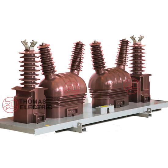
The SZW-35 is a 33kV (IEC-rated) / 35kV (domestic system) cast-resin voltage transformer engineered for high-reliability metering, protection, and control functions in medium-voltage power systems. Unlike traditional oil-immersed designs, the SZW-35 employs vacuum pressure impregnation (VPI) epoxy resin technology to fully encapsulate its primary and secondary windings along with a grain-oriented electrical steel (GOES) core. This construction eliminates fire hazards, prevents oil leakage, and ensures stable dielectric performance across extreme environmental conditions—making it ideal for outdoor substations, industrial facilities, and renewable energy interconnection points.
Operating Principle of Cast-Resin Insulation
Cast-resin insulation in the SZW-35 utilizes a two-component cycloaliphatic epoxy resin system cured under vacuum and pressure. This process removes air voids and moisture, resulting in a homogeneous, void-free solid dielectric with a relative permittivity (εr) of approximately 3.8 and volume resistivity exceeding 1×10¹⁴ Ω·cm at 20°C. The resin’s high tracking resistance (>600 V per IEC 60587) and thermal class F (155°C) rating enable continuous operation under partial discharge levels below 10 pC at 1.2 × Um/√3. The encapsulated windings are mechanically bonded to the core, minimizing vibration-induced micro-movements that could degrade insulation over time. This monolithic structure provides superior resistance to pollution, UV radiation, and thermal cycling compared to oil-paper or SF6-filled alternatives.
Advantages Over Oil-Immersed Designs
The SZW-35 eliminates critical failure modes inherent to oil-immersed VTs. There is no risk of oil leakage, which can cause environmental contamination and insulation degradation. Its solid insulation requires no maintenance related to oil sampling, degassing, or level monitoring. The fire point of epoxy resin exceeds 500°C, classifying the unit as non-flammable per IEC 60695, whereas mineral oil has a flash point near 140°C. Additionally, the compact footprint—typically 30% smaller than equivalent oil-filled units—reduces space requirements in switchgear bays. The absence of a conservator tank and breather simplifies installation and reduces susceptibility to moisture ingress, a leading cause of dielectric failure in humid climates.
Typical Applications Overview
The SZW-35 is deployed in 33/35kV distribution networks where accuracy, safety, and longevity are paramount. Primary use cases include revenue metering at utility substations, overvoltage and undervoltage protection relay inputs, synchro-check circuits for generator synchronization, and harmonic monitoring in industrial plants with nonlinear loads. Its robust design supports operation in coastal areas (Class III pollution per IEC 60815), high-altitude sites (up to 3000 m above sea level with derating), and regions with wide temperature swings (–40°C to +45°C ambient). The transformer’s low thermal time constant ensures rapid stabilization after load transients, critical for digital protective relays requiring precise waveform fidelity.
Technical Specifications
The SZW-35 adheres to stringent electrical and mechanical parameters defined by IEC 61869-3 and GB/T 20840.3. Below is a comprehensive specification table followed by environmental and operational constraints.
| Parameter | Value |
|---|---|
| System Voltage (Um) | 36 kV (IEC), 40.5 kV (GB) |
| Rated Primary Voltage | 33,000 / √3 V (IEC), 35,000 / √3 V (GB) |
| Secondary Voltage Configurations | 100/√3 V, 100 V, or dual outputs (e.g., 100/√3 V + 100 V) |
| Voltage Ratio Accuracy | ±0.2% for 0.2 class; ±0.5% for 0.5 class |
| Accuracy Classes | Metering: 0.2, 0.5; Protection: 3P, 6P |
| Rated Output (per winding) | 10–100 VA (standard); up to 150 VA optional |
| Insulation Level (LI/AC) | 170 kV / 70 kV (IEC); 185 kV / 95 kV (GB) |
| Partial Discharge | <10 pC at 1.2 × Um/√3 |
| Thermal Class | F (155°C) |
| Core Material | Grain-Oriented Electrical Steel (GOES), 0.23 mm thickness |
| Weight | Approx. 120 kg (varies by output configuration) |
Standard Service Conditions
The SZW-35 is rated for standard service conditions per IEC 60060-1: ambient temperature range of –40°C to +45°C, relative humidity up to 100% (condensing), and altitude ≤1000 m. For installations above 1000 m, the power frequency withstand voltage must be reduced by 1% per 100 m increment above 1000 m, per IEC 60071-2. In high-pollution environments (e.g., near chemical plants or coastal zones), creepage distance is enhanced to ≥25 mm/kV (phase-to-ground), satisfying IEC 60815 pollution severity Class III. The unit is designed for continuous operation at 1.2 × rated voltage for up to 8 hours without exceeding thermal limits.
Electrical Performance Parameters
Voltage error and phase displacement are tightly controlled: for a 0.2-class SZW-35 at 80–120% of rated voltage and 25–100% of rated burden, voltage error remains within ±0.2%, and phase error does not exceed ±10 minutes. Burden tolerance is ±10% of nominal value. The magnetizing current at rated voltage is typically <0.5% of rated primary current, ensuring minimal impact on system loading. Frequency response is flat from 48 Hz to 52 Hz, with harmonic distortion (THD) <0.5% under sinusoidal excitation. These characteristics ensure compatibility with modern digital meters and numerical relays requiring high waveform fidelity.
Typical Applications
The SZW-35 serves diverse roles across power infrastructure due to its precision, durability, and compliance with international standards.
Substation Secondary Metering
In 33/35kV utility substations, the SZW-35 provides accurate voltage signals to revenue-class kWh meters and demand recorders. Its 0.2-class accuracy ensures billing integrity, while low phase error minimizes reactive power measurement inaccuracies. Dual-secondary configurations allow one winding to feed billing meters and another to supply SCADA RTUs or power quality analyzers. The transformer’s immunity to electromagnetic interference (EMI) from nearby circuit breakers or busbars ensures stable readings even during switching transients. Installation on live-tank or dead-tank structures is supported via standardized mounting flanges per IEC 61869-3 Annex C.
Industrial Power Distribution
Heavy industries—such as steel mills, petrochemical plants, and data centers—use the SZW-35 for motor protection, capacitor bank control, and arc-flash mitigation systems. In facilities with variable-frequency drives (VFDs), the VT’s low capacitive coupling and high-frequency damping suppress common-mode noise that could distort relay inputs. The 3P or 6P protection class enables reliable operation of overvoltage relays (e.g., 59) and loss-of-potential detectors (27/59). Its cast-resin housing resists chemical vapors and dust accumulation, critical in harsh industrial environments where oil-filled units would require frequent cleaning or replacement.
Renewable Energy Integration
Solar farms and wind parks operating at 35kV grid connection voltages deploy the SZW-35 for grid-synchronization and anti-islanding protection. During cloud transients or wind lulls, rapid voltage fluctuations demand fast-response VTs with minimal hysteresis—achieved through the GOES core’s narrow B-H loop. The transformer supplies voltage signals to synchro-check relays (25) ensuring generator terminals match grid voltage magnitude, phase, and frequency before closing. Its ability to withstand temporary overvoltages (TOVs) up to 1.3 × Un for 1 minute supports ride-through during grid faults, complying with IEEE 1547 and GB/T 19964 grid codes.
Rural and Suburban Distribution Networks
In remote or mountainous regions, the SZW-35’s maintenance-free design reduces operational costs where technician access is limited. It is commonly mounted on pole-top platforms or pad-mounted switchgear to feed single-phase or three-phase metering banks. The unit’s resistance to ice loading (tested per IEC 60507) and UV degradation ensures decades of service without performance drift. In suburban ring-main units (RMUs), its compact size allows integration alongside vacuum interrupters and current transformers without enlarging the enclosure footprint.
Compliance with International Standards
The SZW-35 is certified to both global and Chinese national standards, ensuring interoperability and regulatory acceptance.
IEC 61869-3 Compliance Details
Per IEC 61869-3:2011, the SZW-35 meets all requirements for electromagnetic voltage transformers. Key tests include power frequency withstand (70 kV rms for 1 min between HV-LV and ground), lightning impulse (170 kV peak, 1.2/50 μs wave), and temperature rise (≤60 K for windings at rated burden). Accuracy verification follows Clause 6.4, with tests conducted at 20%, 50%, 80%, 100%, and 120% of rated voltage. The standard mandates that phase error for 0.2 class must not exceed ±10′ at 100% burden and ±15′ at 25% burden. Partial discharge measurements are performed per IEC 60270, with acceptance criteria of ≤10 pC at 1.2 × Um/√3.
GB/T 20840.3 Alignment
GB/T 20840.3-2013 aligns closely with IEC 61869-3 but specifies higher insulation levels for the Chinese 35kV system: lightning impulse withstand of 185 kV and power frequency of 95 kV. The domestic standard also requires additional short-time thermal current testing for VTs used in resonant grounding systems, though this is less relevant for voltage transformers than current transformers. Accuracy classes and burden definitions are identical, but GB/T mandates extended temperature rise tests at 1.5 × rated voltage for 30 seconds to simulate ferroresonance conditions—a scenario more prevalent in Chinese rural networks with long overhead lines.
Testing and Certification Requirements
Full type testing includes 15+ procedures: dielectric tests, accuracy verification, temperature rise, short-circuit withstand (for fault currents on secondary side), and environmental conditioning (thermal shock, humidity). Routine tests for every unit include turns ratio check (±0.2% tolerance), polarity verification, insulation resistance (>1000 MΩ at 2500 V DC), and partial discharge screening. Third-party certification from bodies like KEMA, CESI, or China National Institute of Standardization (CNIS) is required for grid interconnection.
On-Site Testing Procedures
Post-installation commissioning ensures the SZW-35 performs within specifications before energization.
Insulation Resistance Test
Using a 2500 V DC megohmmeter, measure insulation resistance between primary winding and ground, secondary windings and ground, and primary-to-secondary. Acceptance criterion: ≥1000 MΩ at 20°C. Correct for temperature using RT2 = RT1 × 2(T1–T2)/10. Low readings indicate moisture ingress or resin cracking. Perform before and after dielectric tests to detect insulation damage.
Turns Ratio Test
Apply 100–200 V AC to the primary and measure secondary voltage. Calculate ratio as Vp/Vs. Tolerance: ±0.2% for 0.2 class, ±0.5% for 0.5 class. Use a calibrated ratio bridge or digital VT analyzer. Deviations beyond tolerance suggest winding shorts or incorrect tap selection.
Polarity Test
Verify reducing polarity per IEC 61869-3 Figure 5. Apply low-voltage DC pulse to primary; observe secondary voltage direction with an oscilloscope or analog voltmeter. Positive-going primary pulse should yield positive-going secondary pulse on marked terminals. Incorrect polarity causes 180° phase shift, disrupting wattmeter and relay operation.
Power Frequency Withstand Voltage Test
Apply 70 kV rms (IEC) or 95 kV rms (GB) at 50 Hz between HV terminals and grounded base for 1 minute. Use a test transformer with overcurrent protection set to 1 A. No flashover or disruptive discharge permitted. Ramp voltage at 2 kV/s to avoid transient overvoltages.
Open-Circuit Characteristic Test
Gradually increase primary voltage from 0 to 190% of rated value while measuring secondary voltage and excitation current. Plot Vs vs Iexc. Knee point should occur above 150% rated voltage. Excessive magnetizing current below 120% indicates core saturation or shorted turns. This test validates immunity to ferroresonance.
Preventive Maintenance Guide
Although cast-resin VTs require minimal maintenance, periodic checks extend service life beyond 25 years.
Periodic Inspection Schedule
Conduct visual inspections annually: check for surface tracking, cracks, discoloration, or contamination on the resin housing. Clean with deionized water if salt or dust deposits exceed 0.1 mg/cm². Verify terminal tightness (torque: 15 N·m for M10 bolts) and grounding continuity (<0.1 Ω resistance). Every 5 years, perform insulation resistance and partial discharge tests to establish baseline degradation trends.
Fault Diagnosis and Troubleshooting
Common failure modes include secondary winding open-circuit (causing overvoltage on remaining windings), core lamination shorts (increased no-load loss), and terminal corrosion (intermittent metering errors). If secondary voltage drops >5%, disconnect and perform turns ratio and winding resistance tests. Winding resistance imbalance >2% indicates internal fault. Persistent partial discharge >20 pC suggests void formation in resin—requires replacement. Never operate with an open secondary circuit under primary voltage, as this induces dangerous overvoltages.
Conclusion
The SZW-35 33kV cast-resin voltage transformer represents a benchmark in reliability, accuracy, and safety for medium-voltage applications. By leveraging VPI epoxy resin encapsulation and GOES core technology, it eliminates the fire, leakage, and maintenance risks associated with oil-immersed alternatives while delivering metrological performance that meets IEC 61869-3 0.2-class standards. Its robust design withstands harsh outdoor environments—from coastal humidity to alpine cold—and supports critical functions including revenue metering, protective relaying, and renewable energy grid integration. Full compliance with both IEC and GB/T standards ensures global acceptance and seamless interoperability with modern substation automation systems. With a proven service life exceeding 25–30 years under standard operating conditions, the SZW-35 offers utilities and industrial operators a cost-effective, future-proof solution for voltage sensing in 33/35kV networks. Its combination of technical precision, environmental resilience, and regulatory alignment makes it a preferred choice for new installations and legacy system upgrades worldwide.