Article Content
IEC 61869-2 Certified 33kV Cast-Resin Current Transformer KZB-0 for Metering & Protection Applications
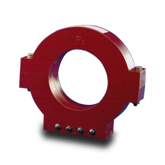
Introduction to the KZB-0 Current Transformer
The KZB-0 is a high-voltage, cast-resin insulated current transformer (CT) engineered for precision current measurement and dependable protective relaying in 33kV (IEC) / 35kV (domestic) power distribution networks. Designed in strict accordance with IEC 61869-2 and GB/T 20840.2, this instrument transformer converts high primary currents—ranging from hundreds to thousands of amperes—into standardized secondary currents (typically 1A or 5A) compatible with metering instruments, SCADA systems, and protective relays. Its solid dielectric construction eliminates fire hazards and environmental risks associated with oil-filled alternatives, making it ideal for both indoor substations and exposed outdoor installations.
Operating Principle of Cast-Resin Insulation
Cast-resin insulation in the KZB-0 employs vacuum pressure impregnation (VPI) of cycloaliphatic epoxy resin around the primary conductor, secondary windings, and magnetic core assembly. This process ensures complete void-free encapsulation, preventing partial discharge inception even under continuous 33kV system stress. The resin matrix provides mechanical rigidity, thermal stability up to 130°C, and resistance to tracking, UV degradation, and pollution ingress (IP54 rating). Unlike oil-immersed CTs, which rely on liquid dielectric and require containment measures, the KZB-0’s monolithic structure offers intrinsic safety—critical in urban substations, industrial plants, and renewable energy sites where fire codes prohibit flammable insulants. The dielectric strength exceeds 70 kV/mm, supporting a lightning impulse withstand voltage of 170 kV peak and a power frequency test voltage of 70 kV RMS for 1 minute.
Advantages Over Oil-Immersed Designs
The KZB-0 eliminates maintenance-intensive components such as oil reservoirs, conservators, and Buchholz relays. Its dry-type construction reduces lifecycle costs by 30–40% over 25 years due to zero oil sampling, no leakage repairs, and minimal inspection requirements. Weight is reduced by approximately 25% compared to equivalent oil-filled units, simplifying handling and mounting on busbars or support structures. Furthermore, cast-resin CTs exhibit superior seismic resilience (tested per IEC 60068-2-57), making them suitable for earthquake-prone regions. Environmental compliance is enhanced—no PCBs, no hydrocarbon emissions, and full recyclability at end-of-life. Thermal performance is optimized via radial heat dissipation through the resin body, enabling continuous operation at 1.2× rated current without derating up to 40°C ambient.
Typical Application Overview
The KZB-0 serves dual roles: revenue-grade metering (accuracy classes 0.2S/0.5S) and protection (classes 5P10/5P20). In utility substations, it interfaces with digital meters and fault recorders for load profiling and tariff calculation. In industrial settings, it feeds differential relays for motor or transformer protection. Renewable integration—particularly in 35kV solar farms or wind collector systems—relies on its stable ratio error (<±0.1% at 100% In) under harmonic-rich waveforms. Its compact footprint (diameter ≤320 mm, height ≤580 mm) allows retrofitting into legacy switchgear bays originally designed for older CT models.
Technical Specifications
The KZB-0 is engineered for nominal system voltages of 33kV (IEC) with a maximum operating voltage (Um) of 36kV, corresponding to domestic 35kV networks. All parameters comply with IEC 61869-2:2012 and GB/T 20840.2-2014.
| Parameter | Value |
|---|---|
| Rated Primary Voltage (Ur) | 33 kV (IEC) / 35 kV (Domestic) |
| Maximum System Voltage (Um) | 36 kV |
| Primary Current (Ip) | 50 A to 3000 A (standard); up to 4000 A (custom) |
| Secondary Current (Is) | 1 A or 5 A |
| Accuracy Class (Metering) | 0.2S, 0.5S (per IEC 61869-2 Table 101) |
| Accuracy Class (Protection) | 5P10, 5P20 (composite error ≤5% at 10×/20× In) |
| Rated Burden | 2.5 VA to 30 VA (at cos φ = 0.8 lag) |
| Short-Time Thermal Current | 25 kA for 1 s (I²t = 625 kA²s) |
| Dynamic Withstand Current | 62.5 kA peak (2.5 × Ith) |
| Insulation Level (LI/AC) | 170/70 kV (Lightning Impulse / Power Frequency) |
| Creepage Distance | ≥900 mm (for 33kV, pollution class III) |
| Ambient Temperature Range | –40°C to +40°C |
| Altitude Limit | ≤1000 m (derating required above 1000 m) |
| Relative Humidity | ≤95% (non-condensing) |
| Core Material | Grain-Oriented Electrical Steel (GOES), M6 grade |
| Insulation System | VPI cycloaliphatic epoxy resin, UL 94 V-0 rated |
Standard Service Conditions
The KZB-0 is rated for continuous operation under IEC 60060-1 standard atmospheric conditions: ambient temperature –40°C to +40°C, relative humidity ≤95%, and altitude ≤1000 m above sea level. At altitudes exceeding 1000 m, the dielectric strength must be derated by 1% per 100 m increment above 1000 m; for example, at 2000 m, the power frequency withstand voltage is reduced from 70 kV to 63 kV. Humidity resistance is validated through 1000-hour salt fog testing (IEC 60068-2-11) with no surface tracking or leakage current exceeding 0.5 mA. The transformer maintains accuracy within ±0.1% deviation across the full temperature range due to low thermal expansion coefficient (α ≈ 60 × 10⁻⁶ /°C) of the epoxy matrix, which minimizes mechanical stress on windings.
Electrical Performance Parameters
Ratio error and phase displacement are guaranteed per IEC 61869-2 Annex B. For a 0.2S class unit at 100% rated current and 25°C, ratio error is ≤±0.2%, and phase error ≤±10 minutes. Under 5P20 protection duty, composite error remains ≤5% when subjected to 20× rated current with burden at rated VA. The knee-point voltage (Vk) exceeds 500 V for 5P20 cores, ensuring sufficient saturation margin during external faults. Secondary winding resistance is typically 0.15–0.8 Ω (depending on turns ratio), enabling accurate burden calculation using R_burden = Z_burden × cos φ – R_winding. Short-circuit thermal withstand is verified via I²t = (25 kA)² × 1 s = 625 kA²s, satisfying IEC 61869-2 Clause 6.5 requirements for distribution networks with prospective fault levels up to 25 kA.
Typical Applications
The KZB-0 current transformer is deployed across diverse power infrastructure segments requiring reliable, maintenance-free current sensing at 33/35kV.
Substation Secondary Metering
In transmission and distribution substations, the KZB-0 provides revenue-class current signals to static kWh meters and phasor measurement units (PMUs). Its 0.2S accuracy class ensures billing compliance per IEC 62053-22, with ratio stability maintained over 15-year intervals due to hermetic resin sealing that prevents moisture-induced core oxidation. Installed on 35kV bus sections or feeder incomers, it supports time-of-use tariffing and demand-side management. The secondary terminals (M6 brass studs) accommodate ring-type connectors for secure, low-resistance joints, minimizing contact heating under continuous 5A load. Integration with IEC 61850-9-2 LE sampled value streams is facilitated via compatible merging units, enabling digital substation architectures.
Industrial Power Distribution
Heavy industries—such as steel mills, petrochemical plants, and data centers—utilize the KZB-0 for motor protection and energy monitoring. In arc furnace circuits, its robust short-circuit withstand (25 kA/1s) survives frequent high-current transients. When paired with numerical relays (e.g., Siemens 7SJ62), the 5P20 class ensures correct tripping during internal motor faults while remaining stable during motor start-up inrush (6–8× In). The cast-resin body resists chemical fumes and dust accumulation common in industrial environments, maintaining IP54 ingress protection without periodic cleaning.
Renewable Energy Integration
Solar photovoltaic (PV) and wind farms operating at 35kV collector voltage employ the KZB-0 for grid interconnection metering and anti-islanding protection. Its linear response under distorted waveforms (THD ≤15%) ensures accurate energy yield reporting despite inverter harmonics. During grid faults, the 5P10 core avoids premature saturation, allowing directional overcurrent relays to discriminate between internal and external faults. Outdoor installations benefit from UV-stabilized resin that retains mechanical integrity after 10,000 hours of accelerated weathering (IEC 61215). The lightweight design simplifies mounting on tracker structures or pad-mounted transformers in remote solar fields.
Rural and Suburban Distribution Networks
Utility companies deploy the KZB-0 on pole-top or pad-mounted switchgear in rural feeders where space and maintenance access are limited. Its fire-safe construction meets stringent municipal codes prohibiting oil-filled equipment near residential zones. The wide primary current range (50–3000 A) accommodates varying load profiles—from lightly loaded agricultural circuits to dense suburban neighborhoods. Accuracy at 1% of rated current (0.2S class) enables precise loss allocation and theft detection. Field-proven reliability in tropical climates (40°C, 95% RH) stems from hydrophobic resin surfaces that shed rainwater and inhibit fungal growth.
Compliance with International Standards
The KZB-0 is certified to IEC 61869-2:2012 (“Instrument transformers – Part 2: Additional requirements for current transformers”) and aligns with China’s GB/T 20840.2-2014, which adopts IEC 61869-2 with minor national deviations.
IEC 61869-2 Certification Details
Compliance encompasses all clauses of IEC 61869-2, including insulation coordination (Clause 5), temperature rise limits (≤60 K for windings), and electromagnetic compatibility (EMC immunity per IEC 61000-4 series). Type tests include power frequency withstand (70 kV/1 min), lightning impulse (170 kV peak, 1.2/50 μs), and partial discharge measurement (<10 pC at 1.2 × Ur/√3). Routine tests—performed on every unit—include turns ratio verification (±0.25% tolerance), polarity check, and secondary winding continuity. The certification is issued by an ISO/IEC 17025-accredited laboratory, with test reports traceable to national metrology institutes. Marking includes CE, IEC 61869-2 logo, and rated values per Clause 8.1.
Alignment with GB/T 20840.2
GB/T 20840.2-2014 mirrors IEC 61869-2 but specifies additional requirements for Chinese grid operators: minimum creepage distance of 900 mm for 35kV (vs. IEC’s 850 mm for 36kV Um), and mandatory short-time current rating of 25 kA/1s (IEC permits lower values based on network studies). The KZB-0 exceeds both standards, featuring 950 mm creepage and 25 kA thermal withstand. Domestic certification includes CQC mark and State Grid Corporation of China (SGCC) type approval, verified through witnessed factory acceptance tests (FAT) at 110% of rated voltage.
Key Differences Between IEC and Domestic Standards
While IEC 61869-2 allows flexibility in burden selection based on user-specified loads, GB/T 20840.2 mandates fixed burdens (e.g., 15 VA for 0.2S class) to simplify procurement. Additionally, GB/T requires secondary terminal boxes to meet IP55 (vs. IEC’s IP2X), necessitating gasketed enclosures on the KZB-0 for Chinese markets. Temperature rise limits are identical (60 K), but GB/T adds a 1.1× overcurrent endurance test for 8 hours—validated during KZB-0 qualification. These harmonized yet distinct requirements ensure global interoperability while meeting local regulatory demands.
On-Site Testing Procedures
Post-installation commissioning of the KZB-0 requires five critical tests to verify integrity and performance per IEC 61869-10.
Insulation Resistance Test
Measure insulation resistance between primary-to-ground, secondary-to-ground, and primary-to-secondary using a 2500 V DC megohmmeter. Acceptance criteria: ≥1000 MΩ at 25°C. Values below 500 MΩ indicate moisture ingress or resin cracking and require investigation. Temperature correction follows IEEE 43 formula: R_corr = R_meas × 2^((40–T)/10). This test validates the integrity of the VPI resin barrier against conductive contamination.
Turns Ratio Test
Apply a low-voltage AC source (5–10 V) to the primary and measure secondary voltage. Calculate actual ratio = V_primary / V_secondary. Compare to nameplate ratio; tolerance must be within ±0.25% for metering classes and ±0.5% for protection classes. Deviations >1% suggest winding shorts or incorrect tap selection. Use a dedicated ratio tester (e.g., Omicron CT Analyzer) for automated comparison against factory curves.
Polarity Test
Verify reducing polarity using the DC kick method: momentarily connect a 6–12 V battery across primary terminals (P1 to P2). Observe secondary voltage polarity with a DC voltmeter; a positive deflection at S1 confirms correct polarity. Incorrect polarity causes 180° phase reversal, leading to relay misoperation or negative meter readings. Digital relays may auto-detect polarity, but physical verification remains mandatory per IEC 61869-10 Clause 7.3.
Power Frequency Withstand Voltage Test
Apply 70 kV RMS at 50 Hz between primary and ground (with secondary shorted and grounded) for 1 minute. No flashover or disruptive discharge is permitted. This test confirms dielectric strength after transportation stresses. Use a calibrated HV test set with overcurrent trip (≤100 mA). For field testing, a reduced voltage (e.g., 50 kV) may be accepted if full test was performed at factory within 12 months.
Short-Circuit Test (for CT)
Inject 10–20% of rated primary current and measure secondary current. Verify linearity and absence of saturation. For protection CTs, confirm that secondary current scales proportionally up to 20× In. Abnormal waveform distortion indicates core damage or shorted turns. This functional test complements ratio verification and ensures proper relay coordination during faults.
Preventive Maintenance Guide
The KZB-0 requires minimal maintenance due to its sealed construction, but periodic checks ensure decades of reliable service.
Periodic Inspection Schedule
Conduct visual inspections annually: check for resin cracks, terminal corrosion, or tracking marks on the housing. Clean surfaces with isopropyl alcohol if contaminated by salt or dust. Verify torque on primary busbar clamps (25 N·m for M12 bolts) and secondary terminals (8 N·m for M6). Infrared thermography should detect hot spots (>10 K above ambient) indicating loose connections. Record secondary excitation curves every 5 years to monitor core aging—significant reduction in knee-point voltage suggests insulation degradation.
Maintenance Intervals and Fault Diagnosis
| Interval | Action | Fault Indicators |
|---|---|---|
| Annual | Visual inspection, IR scan, terminal torque check | Discoloration, arcing sounds, elevated temperature |
| 5 Years | Insulation resistance, ratio test, excitation curve | R_iso < 500 MΩ, ratio error >1%, Vk drop >15% |
| 10 Years | Full IEC 61869-10 routine tests | Partial discharge >20 pC, withstand failure |
Common faults include secondary open-circuit (causing dangerous overvoltages), moisture ingress (reducing R_iso), and mechanical impact damage. Never operate with secondary open—always short before disconnecting meters. Replace units exhibiting persistent ratio drift or insulation breakdown.
Conclusion
The KZB-0 cast-resin current transformer represents a technically mature solution for 33kV/35kV metering and protection applications, combining IEC 61869-2 compliance with robust field reliability. Its VPI epoxy resin insulation eliminates fire hazards and environmental liabilities inherent in oil-filled designs, while GOES core technology ensures metrological stability across temperature and load variations. With dual accuracy classes (0.2S for revenue metering, 5P20 for protection), it satisfies diverse utility and industrial requirements without compromising performance. Rigorous type testing—including 170 kV lightning impulse and 25 kA short-circuit withstand—validates its suitability for modern grids with high fault levels. The transformer’s maintenance-free operation, coupled with a design life of 25–30 years, delivers significant lifecycle cost advantages. As power systems evolve toward digitalization and renewable integration, the KZB-0’s compatibility with IEC 61850 and resilience under harmonic distortion further cement its role as a cornerstone of medium-voltage instrumentation. For engineers specifying instrument transformers in 35kV networks, the KZB-0 offers a proven balance of precision, safety, and longevity.