Article Content
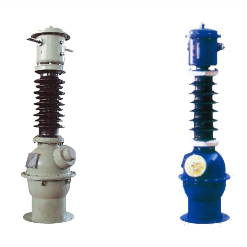
CT-35K 33kV Cast-Resin Current Transformer for Substation Metering and Protection – IEC 61869-2 Certified
Introduction to the CT-35K Current Transformer
The CT-35K is a medium-voltage cast-resin current transformer engineered for reliable operation in 33kV (IEC) / 35kV (domestic) power systems. Designed per IEC 61869-2 and GB/T 20840.2, it provides accurate current transformation for protective relaying, revenue metering, and system monitoring. Its core function is to proportionally reduce high primary currents—ranging from hundreds to tens of thousands of amperes—to standardized secondary outputs of 1 A or 5 A, while maintaining galvanic isolation between the high-voltage primary circuit and low-voltage instrumentation.
Cast-Resin Insulation Technology
The CT-35K employs vacuum pressure impregnation (VPI) epoxy resin casting, which fully encapsulates the primary conductor, secondary windings, and magnetic core in a homogeneous, void-free dielectric matrix. This process eliminates air pockets that could lead to partial discharges under sustained overvoltage conditions. The resin formulation includes silica fillers to enhance thermal conductivity (≈0.8 W/m·K) and UV stabilizers for outdoor durability. Unlike oil-filled alternatives, cast-resin insulation is non-flammable, requires no maintenance for fluid levels or gas pressure, and exhibits superior resistance to environmental contaminants such as salt fog, dust, and industrial pollutants. The solid insulation system achieves a relative permittivity (εr) of 4.2–4.8 and volume resistivity exceeding 1×10¹⁴ Ω·cm at 20°C, ensuring stable dielectric performance across the operational temperature range of –40°C to +40°C.
Advantages Over Oil-Immersed Designs
Compared to traditional oil-immersed current transformers, the CT-35K offers significant operational and safety benefits. The absence of flammable insulating oil eliminates fire hazards, making it suitable for indoor substations, urban switchyards, and confined industrial facilities where fire codes restrict hydrocarbon-based equipment. Its monolithic construction prevents moisture ingress—a common failure mode in oil units—and eliminates the need for periodic oil sampling, degassing, or bushing maintenance. Additionally, the compact footprint (typically 30–40% smaller than equivalent oil units) reduces structural loading on support insulators and facilitates retrofitting in space-constrained installations. The cast-resin body also dampens electromagnetic vibrations, reducing audible noise to below 45 dB(A) at rated current, which is critical in noise-sensitive environments.
Typical Deployment Scenarios
The CT-35K is predominantly deployed in 33kV transmission and distribution networks, including utility-owned substations, industrial plant switchgear, and renewable energy interconnection points. In grid applications, it interfaces with numerical relays (e.g., SEL-421, Siemens 7UT6) for overcurrent, differential, and distance protection schemes. For revenue metering, it meets Class 0.2S accuracy requirements under IEC 61869-2, enabling precise kWh billing even at 5% of rated current. In wind and solar farms, its robust design withstands frequent switching transients and harmonic distortion from inverters. The unit is certified for both indoor and outdoor use, with optional hydrophobic coatings for coastal or high-humidity regions.
Technical Specifications
The CT-35K adheres to stringent electrical and mechanical parameters defined by international standards. Below is a representative specification table for a typical configuration; actual values may vary based on customer order code.
| Parameter | Value |
|---|---|
| Rated Voltage (Um) | 33 kV (IEC) / 35 kV (GB) |
| Primary Current (Ip) | 50 A to 4000 A (standard); up to 6300 A (custom) |
| Secondary Current (Is) | 1 A or 5 A |
| Current Ratio | Adjustable via multi-tap secondary (e.g., 1200/1 A, 1200/5 A) |
| Accuracy Class (Metering) | 0.2S, 0.5S per IEC 61869-2 |
| Accuracy Class (Protection) | 5P10, 5P20, 10P10, 10P20 |
| Rated Output (VA) | 2.5 VA to 30 VA (at rated burden) |
| Short-Time Thermal Current (Ith) | 25 kA for 1 s (standard); 40 kA/1s optional |
| Dynamic Withstand Current (Idyn) | 62.5 kA peak (2.5 × Ith) |
| Power Frequency Withstand Voltage | 70 kV rms, 1 min (phase-to-earth) |
| Lightning Impulse Withstand Voltage | 170 kV peak (1.2/50 μs wave) |
| Insulation Material | VPI epoxy resin with silica filler |
| Magnetic Core | Grain-Oriented Electrical Steel (GOES), M4 grade |
| Ambient Temperature Range | –40°C to +40°C |
| Maximum Altitude | 1000 m above sea level (derating required >1000 m) |
Standard Service Conditions
The CT-35K is rated for continuous operation under IEC 60060-1 standard atmospheric conditions: ambient temperature between –40°C and +40°C, relative humidity ≤95% (non-condensing), and altitude ≤1000 m. At altitudes exceeding 1000 m, the dielectric strength must be derated by 1% per 100 m increment above 1000 m. For example, at 2000 m, the power frequency withstand voltage is reduced from 70 kV to 63 kV. The unit is designed for three-phase systems with nominal frequency of 50 Hz or 60 Hz; frequency deviations beyond ±2% may affect ratio error and phase displacement. Installation must ensure adequate clearance distances: minimum 300 mm phase-to-phase and 250 mm phase-to-ground for 33kV systems per IEC 61936-1.
Core and Winding Design
The magnetic circuit utilizes M4-grade grain-oriented electrical steel (GOES) with a maximum specific loss of 1.0 W/kg at 1.7 T and 50 Hz. Laminations are annealed after cutting to minimize residual stress and hysteresis losses. Secondary windings consist of enameled copper wire (Class H insulation, 180°C rating) wound directly onto the core leg, with interlayer insulation of Nomex® paper. Multi-ratio configurations employ bifilar winding techniques to maintain consistent leakage inductance across taps. The primary conductor is a solid copper rod (for ratings ≤1250 A) or hollow copper tube (for ≥1600 A) to accommodate busbar insertion. All terminations use tinned copper studs with M12 or M16 threads, rated for 125°C continuous operation.
Typical Applications
The CT-35K serves diverse roles across modern power infrastructure, leveraging its high accuracy, robust insulation, and compliance with global standards.
Substation Secondary Metering
In utility substations, the CT-35K provides Class 0.2S current signals to revenue-grade meters (e.g., Landis+Gyr E650, Itron Centron). Its low ratio error (<±0.2% at 100% In) and phase displacement (<±10 minutes) ensure billing accuracy even under light-load conditions (down to 1% In for 0.2S class). The transformer’s low burden requirement (as low as 2.5 VA) minimizes voltage drop in long secondary circuits, preserving signal integrity over distances up to 200 meters. It is commonly installed on 33kV feeder breakers, transformer incomers, and capacitor bank feeders where precise energy accounting is mandated by regulatory authorities.
Industrial Power Distribution
Heavy industries—including steel mills, petrochemical plants, and data centers—deploy the CT-35K for motor protection, load monitoring, and harmonic analysis. In arc furnace applications, its 5P20 accuracy class ensures relay coordination during high-magnitude fault currents (up to 20× rated current). The cast-resin housing resists chemical corrosion from sulfur compounds and chlorine vapors prevalent in refineries. For variable frequency drive (VFD) loads, the GOES core maintains linearity despite 5th and 7th harmonic currents, preventing saturation-induced measurement errors.
Renewable Energy Integration
Solar photovoltaic (PV) and wind farms utilize the CT-35K at the point of interconnection (POI) to grid operators. During cloud transients or wind gusts, rapid current fluctuations challenge transformer linearity; the CT-35K’s low remanence (<0.3 T) enables fast recovery from transient saturation. Its 10P10 class supports anti-islanding protection schemes requiring accurate current measurement up to 10× rated current. Inverter-based resources generate high-frequency harmonics (up to 2 kHz); the solid resin insulation suppresses capacitive coupling that could distort secondary signals. Units are often mounted on pole-top structures in remote locations, where maintenance-free operation is essential.
Rural and Suburban Distribution Networks
For rural electrification projects, the CT-35K’s outdoor-rated design (IP54 ingress protection) withstands monsoons, sandstorms, and temperature extremes. It is integrated into 33kV ring main units (RMUs) for sectionalizing and fault location. In suburban areas, compact dimensions allow installation on existing poles without structural reinforcement. The 5 A secondary output simplifies compatibility with legacy electromechanical relays still in service. Utilities leverage its multi-ratio capability to standardize inventory—e.g., a single 2000/1-5 A unit can serve both metering (1 A tap) and protection (5 A tap) functions.
Compliance with International Standards
The CT-35K is engineered to satisfy both global and regional regulatory frameworks, ensuring interoperability and safety across markets.
IEC 61869-2 Certification
As a dedicated current transformer, the CT-35K complies fully with IEC 61869-2:2012 (“Instrument transformers – Part 2: Additional requirements for current transformers”). This standard defines test methods for accuracy verification, thermal rating, and short-circuit performance. Key requirements include: ratio error and phase displacement measured at 5%, 20%, 100%, and 120% of rated current; temperature rise limited to 60 K for windings (measured by resistance method); and short-time current withstand verified at 25 kA/1s without mechanical damage or permanent accuracy shift. The manufacturer provides a type test report issued by an ISO/IEC 17025-accredited laboratory, including partial discharge measurements (<10 pC at 1.2 Um/√3).
Alignment with GB/T 20840.2
For Chinese domestic markets, the CT-35K meets GB/T 20840.2-2014, which largely harmonizes with IEC 61869-2 but includes localized requirements. Notably, GB/T mandates a higher lightning impulse withstand voltage (185 kV vs. IEC’s 170 kV) and specifies creepage distance based on pollution severity (e.g., 25 mm/kV for heavy pollution zones). The standard also requires flame retardancy testing per GB/T 5169.16 (equivalent to IEC 60695-11-10), where the resin must achieve V-0 rating in vertical burning tests. While accuracy classes align (0.2S, 5P20, etc.), GB/T defines burden in ohms rather than VA, necessitating impedance conversion during system design.
Testing and Certification Documentation
Each CT-35K unit undergoes routine tests per IEC 61869-2 Clause 7, including: power frequency withstand (70 kV/1 min), partial discharge (<10 pC at 1.2×33 kV/√3), and turns ratio verification (±0.1% tolerance). Type tests—conducted on prototype batches—include temperature rise, short-circuit, and dynamic withstand. Certification is evidenced by CE marking (for EU), CQC mark (for China), and ANSI C57.13 compliance documentation for North American projects. Test reports include calibrated instrument traceability to NIST or PTB standards.
On-Site Testing Procedures
Post-installation verification ensures the CT-35K performs within specified tolerances before energization.
Insulation Resistance Test
Using a 5 kV DC megohmmeter, measure insulation resistance between primary-to-secondary, primary-to-ground, and secondary-to-ground. Acceptance criteria: ≥10,000 MΩ at 20°C. Correct for temperature using RT2 = RT1 × 2(T1–T2)/10. Values below 1,000 MΩ indicate moisture ingress or resin cracking and require investigation. Perform before and after power frequency withstand testing to detect insulation degradation.
Turns Ratio Test
Apply a low-voltage AC source (5–10 V) to the secondary winding and measure induced primary voltage. Calculate ratio as Vp/Vs; compare to nameplate. Tolerance: ±0.1% for metering classes, ±0.5% for protection classes. Alternatively, use a dedicated ratio tester injecting primary current (e.g., 10 A) and measuring secondary output. Ensure secondary burden does not exceed 10% of rated VA during test to avoid loading errors.
Polarity Verification
Confirm reducing polarity (IEC standard) using a 1.5 V DC battery and analog voltmeter. Connect battery (+) to primary P1 and (–) to P2; connect voltmeter (+) to secondary S1 and (–) to S2. Momentary closure should produce a positive kick on the meter. Incorrect polarity compromises differential protection schemes and causes metering reversal. Document results with timestamped oscillograph if available.
Power Frequency Withstand Voltage Test
Apply 70 kV rms (50 Hz) between primary and grounded secondary/core for 1 minute. Use a calibrated test transformer with overcurrent trip set at 1.5× expected capacitive current (typically 5–10 mA). No flashover or disruptive discharge constitutes pass. Reduce voltage gradually post-test to avoid transient overvoltages. Perform only after insulation resistance exceeds 5,000 MΩ.
Short-Circuit Withstand Verification
While full short-circuit testing is impractical on-site, verify mechanical integrity by inspecting for loose windings or core movement after transport. Check terminal tightness to torque specs (e.g., 35 N·m for M16 studs). Review factory short-circuit test certificate confirming 25 kA/1s withstand without deformation. For critical applications, perform a low-level impedance test (Z = V/I at 10 A) and compare to baseline; >5% deviation suggests internal damage.
Preventive Maintenance Guide
Although cast-resin CTs are maintenance-free by design, periodic checks extend service life and prevent unexpected failures.
Annual Visual and Electrical Inspection
Inspect housing for cracks, tracking marks, or discoloration indicating partial discharge. Clean surface with isopropyl alcohol to remove conductive dust. Verify secondary terminals are tight and corrosion-free; re-torque to manufacturer specs. Measure insulation resistance annually; a 50% drop from baseline warrants further investigation. Check grounding continuity between transformer base and substation grid (<0.1 Ω resistance).
Five-Year Comprehensive Assessment
Every five years, perform partial discharge measurement using IEC 60270-compliant equipment. Acceptable level: <10 pC at 1.2×(33 kV/√3). Conduct turns ratio and polarity tests to detect winding deformation from short-circuit events. Thermographic scan under load should show uniform temperature distribution; hot spots >10 K above ambient indicate poor connections or core issues. Update maintenance records with all findings.
Maintenance Intervals and Fault Diagnosis
| Interval | Action | Fault Indicators |
|---|---|---|
| Annually | Visual inspection, IR scan, insulation resistance | Cracks, carbon tracks, IR >5000 MΩ |
| 5 Years | Partial discharge, ratio test, thermography | PD >15 pC, ratio error >0.5% |
| After Fault | Full electrical tests, mechanical check | Loose terminals, distorted housing |
Common failure modes include secondary open-circuit (causing core saturation and insulation breakdown) and moisture ingress through damaged sheds. Never operate with secondary open—always short-circuit terminals during maintenance.
Conclusion
The CT-35K 33kV cast-resin current transformer represents a benchmark in medium-voltage instrumentation, combining decades of engineering refinement with modern materials science. Its VPI epoxy resin insulation delivers unmatched reliability in harsh environments, eliminating the fire risks and maintenance burdens associated with oil-filled alternatives. Precision-engineered with GOES cores and multi-tap secondaries, it satisfies the most demanding accuracy requirements—from Class 0.2S revenue metering to 10P20 protection under extreme fault conditions. Full compliance with IEC 61869-2 and GB/T 20840.2 ensures global acceptance, while rigorous factory and field testing protocols guarantee performance consistency. With a design life exceeding 25–30 years under standard operating conditions, the CT-35K minimizes lifecycle costs through zero scheduled maintenance and exceptional resilience to electrical, thermal, and environmental stressors. For utilities, industrial operators, and renewable developers seeking a future-proof solution for 33kV/35kV systems, the CT-35K provides the accuracy, safety, and longevity required for critical power infrastructure.