Article Content
For Substation Metering & Protection: DZC-3 11kV Cast-Resin Voltage Transformer per IEC 61869-3
Introduction to the DZC-3 Voltage Transformer
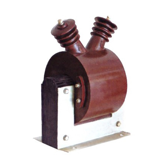
The DZC-3 is a single-phase, cast-resin insulated voltage transformer (VT) engineered for precision voltage measurement, protective relaying, and energy metering in 11kV (IEC) / 10kV (domestic) medium-voltage power systems. Its design leverages vacuum pressure impregnation (VPI) epoxy resin technology to encapsulate high-purity grain-oriented electrical steel (GOES) cores and copper windings, delivering superior dielectric strength, mechanical robustness, and long-term stability under thermal and electrical stress.
Operating Principle of Cast-Resin Insulation
Cast-resin insulation in the DZC-3 employs a two-component cycloaliphatic epoxy system processed under vacuum and pressure to eliminate voids and moisture ingress. This monolithic encapsulation provides a dielectric constant of approximately 4.5 and volume resistivity exceeding 1×10¹⁴ Ω·cm at 20°C. Unlike oil-filled alternatives, the solid resin matrix prevents tracking, corona discharge, and environmental contamination. The VPI process ensures complete impregnation of inter-turn and layer-to-layer insulation, resulting in a partial discharge inception voltage (PDIV) greater than 1.2 times the rated system voltage (13.2 kV rms). This enables reliable operation even in polluted or humid environments up to 95% relative humidity without condensation.
Advantages Over Oil-Immersed Designs
Compared to traditional oil-immersed VTs, the DZC-3 eliminates fire hazards, oil leakage risks, and maintenance-intensive oil testing. Its dry-type construction reduces weight by 30–40%, simplifies transportation, and allows installation in confined spaces such as indoor switchgear or building substations. The absence of flammable materials complies with IEC 61869-3’s requirements for non-flammable instrument transformers in public-access areas. Additionally, the thermal time constant of cast-resin is lower than oil, enabling faster heat dissipation during transient overvoltages. The DZC-3 exhibits a temperature rise of ≤55 K above ambient at rated load, well within IEC limits, ensuring stable accuracy over its 25–30-year design life.
Typical Application Overview
The DZC-3 is deployed across utility substations, industrial plants, commercial complexes, and renewable energy facilities where accurate voltage sensing is critical. It interfaces directly with digital protective relays (e.g., overvoltage, undervoltage, directional earth fault), revenue-grade kWh meters, and SCADA systems. Its dual secondary windings—typically one for metering (Class 0.2 or 0.5) and one for protection (Class 3P)—allow simultaneous high-accuracy measurement and fault detection without cross-interference. The compact footprint (approx. 320 mm height × 180 mm width) facilitates retrofitting into legacy panels originally designed for older VT models.
Technical Specifications
The DZC-3 adheres to stringent electrical and mechanical parameters defined by IEC 61869-3 and GB/T 20840.3. Key specifications are summarized below:
| Parameter | Value |
|---|---|
| Primary Voltage (Up) | 11,000 V (IEC) / 10,000 V (GB) |
| Secondary Voltage (Us) | 100 V or 100/√3 V (standard); 110 V optional |
| Voltage Ratio | 11,000/100 V; 11,000/100/√3 V; 10,000/100 V |
| Accuracy Class (Metering) | 0.2, 0.5 (per IEC 61869-3) |
| Accuracy Class (Protection) | 3P, 6P |
| Rated Output (per winding) | 10–100 VA (metering); 50–200 VA (protection) |
| Insulation Level (LI/AC) | 75 kV lightning impulse / 28 kV power frequency (1 min) |
| Short-Time Thermal Withstand | 1 s at 25× rated primary current (for fault conditions) |
| Ambient Temperature Range | –25°C to +40°C (indoor); –40°C to +45°C (outdoor variants) |
| Relative Humidity | Up to 95% non-condensing |
| Altitude Limit | ≤1,000 m (derating required above 1,000 m) |
Standard Service Conditions
The DZC-3 is rated for continuous operation under standard service conditions per IEC 61869-3: ambient temperature not exceeding +40°C, daily average ≤35°C, and relative humidity ≤95%. At altitudes above 1,000 m, the dielectric strength must be derated by 1% per 100 m increment due to reduced air density. For example, at 2,000 m, the power frequency withstand voltage is reduced from 28 kV to 25.2 kV. The transformer is suitable for both indoor switchgear (IP2X enclosure compatibility) and outdoor pole-mounted installations when equipped with UV-stabilized resin and hydrophobic sheds.
Core and Winding Design
The magnetic circuit uses CRGO (cold-rolled grain-oriented) silicon steel laminations with a maximum core loss of 1.2 W/kg at 1.7 T and 50 Hz. Primary windings consist of enameled copper wire with Class F (155°C) insulation, while secondary windings use double-insulated magnet wire to meet creepage distance requirements (>25 mm/kV). The turns ratio tolerance is ±0.25% for metering classes and ±1.0% for protection classes, verified during factory testing. Burden compatibility is guaranteed for inductive, resistive, and mixed loads within the specified VA rating.
Typical Applications
The DZC-3 serves diverse roles in modern power infrastructure, combining metrological precision with rugged reliability.
Substation Secondary Metering
In 11kV distribution substations, the DZC-3 supplies scaled-down voltage signals to Class 0.2S or 0.5S revenue meters for accurate billing. Its low phase error (<±10 minutes at 0.2 class) ensures compliance with EN 50470 and DL/T 614 standards. When connected in V-V or open-delta configurations, it enables three-phase voltage monitoring using only two units. The transformer’s low no-load losses (<15 W) minimize phantom energy consumption in lightly loaded networks, contributing to grid efficiency.
Industrial Power Distribution
Within manufacturing facilities, the DZC-3 interfaces with motor protection relays (e.g., 27/59 functions) and power quality analyzers. Its 3P-class protection winding maintains accuracy up to 5× rated voltage during transient overvoltages, enabling reliable detection of ground faults in resistance-grounded systems. In arc flash mitigation schemes, fast-acting undervoltage relays triggered by the DZC-3 can de-energize busbars within 2–3 cycles, reducing incident energy.
Renewable Energy Integration
Solar farms and wind parks utilize the DZC-3 for grid synchronization and anti-islanding protection. During voltage sags (e.g., LVRT events), the VT’s linear response down to 0.1× Un allows inverters to remain connected per IEEE 1547 or GB/T 19964 requirements. Its immunity to DC offset—critical in converter-dominated grids—ensures stable operation without core saturation, unlike some iron-core CTs.
Rural and Suburban Distribution Networks
In remote feeders with long cable runs, the DZC-3’s high insulation level (75/28 kV) withstands switching surges from capacitor bank energization. Its maintenance-free design reduces operational costs in areas with limited technical personnel. When installed on pole-top platforms, the unit’s hydrophobic resin surface sheds rainwater, preventing flashovers during wet pollution events.
Backup Power and UPS Systems
Critical facilities (hospitals, data centers) employ the DZC-3 to monitor utility voltage for automatic transfer switch (ATS) logic. Its fast response time (<20 ms to 90% output after step change) ensures seamless switchover during outages. The dual secondary outputs allow one winding to feed the ATS controller while the other supplies a local HMI display.
Compliance with International Standards
The DZC-3 is fully compliant with IEC 61869-3:2011 (“Instrument transformers – Part 3: Inductive voltage transformers”) and harmonized with China’s GB/T 20840.3-2013.
IEC 61869-3 Compliance Details
IEC 61869-3 mandates rigorous performance criteria for accuracy, thermal stability, and dielectric integrity. The DZC-3 meets all Type Tests, including:
- Temperature rise test: ≤55 K at 1.2× rated burden
- Short-circuit withstand: 25× In for 1 s without damage
- Partial discharge: ≤10 pC at 1.2 Um/√3
- Accuracy verification: tested at 25%, 50%, 100%, and 120% of rated voltage
The standard also requires marking of rated insulation level (e.g., “75/28”), accuracy class, and thermal burden on the nameplate—features implemented on all DZC-3 units.
Alignment with GB/T 20840.3
GB/T 20840.3 adopts IEC 61869-3 with minor national deviations. Key differences include:
- Domestic systems reference 10kV instead of 11kV nominal voltage
- Mandatory short-time thermal current rating of 25 kA for 1 s
- Stricter humidity test: 95% RH at 40°C for 48 hours
The DZC-3 is dual-marked for both standards, facilitating export and domestic deployment. Factory test reports include separate IEC and GB compliance certificates issued by CNAS-accredited laboratories.
Testing and Certification Requirements
Each DZC-3 undergoes Routine Tests per IEC 61869-3 Clause 8:
- Power frequency withstand: 28 kV rms for 1 minute between HV-LV and HV-ground
- Turns ratio verification: ±0.25% tolerance for metering windings
- Insulation resistance: >1,000 MΩ at 2,500 V DC (HV to LV/ground)
- Polarity check: confirmed as subtractive (reducing) polarity
Type Tests are performed annually on production samples, with results archived for 10 years. The transformer carries CE, CCC, and CQC marks, confirming conformity with EU and Chinese regulatory frameworks.
On-Site Testing Procedures
Post-installation verification ensures the DZC-3 performs within specifications before commissioning.
Insulation Resistance Test
Using a 2,500 V DC megohmmeter, measure insulation resistance between primary and secondary/ground terminals. Acceptance criterion: ≥1,000 MΩ at 20°C. If readings fall below 500 MΩ, investigate for moisture ingress or surface contamination. Clean terminals with isopropyl alcohol and retest. Record ambient temperature and humidity, as resistance decreases by ~50% per 10°C rise.
Turns Ratio Test
Apply 100–200 V AC to the primary and measure secondary voltage with a calibrated true-RMS meter. Calculate ratio as Vp/Vs. Tolerance: ±0.25% for 0.2/0.5 class windings; ±1.0% for 3P/6P. Example: For 11,000/100 V VT, measured ratio must be 110.0 ±0.275. Use a dedicated ratio tester (e.g., Omicron CT Analyzer) for automated comparison against nameplate values.
Polarity Test
Connect a 6–12 V battery momentarily between primary terminals (H1 to H2). Observe secondary voltage polarity with a DC voltmeter: a positive deflection at X1 (relative to X2) confirms subtractive polarity. Incorrect polarity causes 180° phase shift, leading to relay misoperation or meter reversal. Verify against the terminal diagram stamped on the housing.
Power Frequency Withstand Voltage Test
Apply 28 kV rms (50 Hz) for 1 minute between primary and secondary/ground. Use a calibrated test transformer with overcurrent protection set to 50 mA. Any flashover, smoke, or sustained current increase indicates insulation failure. Perform this test only if factory certification is unavailable or after major repairs. Reduce voltage to 80% (22.4 kV) for repeat tests.
Open-Circuit Characteristic Test
Gradually increase primary voltage from 0 to 120% Un (13.2 kV) while measuring secondary voltage and excitation current. Plot Vs vs. Iexc. The knee point should exceed 110% Un, indicating no core saturation under normal operation. Excessive excitation current (>5 mA at 100% Un) suggests shorted turns or degraded core lamination insulation.
Preventive Maintenance Guide
Although cast-resin VTs require minimal maintenance, periodic checks extend service life and prevent unexpected failures.
Annual Inspection Protocol
Visually inspect for:
- Cracks, tracking, or discoloration on resin surface
- Loose terminal connections or corrosion
- Dust accumulation (clean with dry air at <0.5 MPa)
Thermographically scan terminals under load; temperature differentials >10°C indicate high-resistance joints. Verify secondary wiring integrity—broken leads can cause open-circuit overvoltage on the primary side. Record secondary voltage under no-load and full-load conditions; deviations >0.5% warrant further testing.
Maintenance Intervals and Fault Diagnosis
| Interval | Action |
|---|---|
| 1 year | Visual inspection, IR thermography, connection torque check |
| 5 years | Insulation resistance, turns ratio, open-circuit test |
| 10 years | Full IEC routine test suite (if accessible) |
Common faults include:
- High ratio error: Caused by shorted secondary turns or core degradation. Diagnose via open-circuit test.
- Low insulation resistance: Indicates moisture absorption. Bake at 80°C for 24 hours in dry oven, then retest.
- No output: Check for blown fuses in secondary circuit or open primary connection.
Never operate with an open secondary circuit—this can induce dangerous overvoltages (>10 kV) on the primary.
Conclusion
The DZC-3 11kV cast-resin voltage transformer represents a benchmark in medium-voltage instrumentation, combining IEC 61869-3-certified accuracy with the durability of epoxy resin encapsulation. Its dual-winding architecture supports concurrent metering (Class 0.2/0.5) and protection (3P/6P) functions without compromise, while the GOES core ensures low losses and stable performance across temperature extremes. Engineered for 25–30 years of maintenance-free service, the DZC-3 eliminates the fire risks and environmental liabilities associated with oil-filled alternatives. Rigorous factory testing—including partial discharge, thermal withstand, and ratio verification—guarantees reliability in critical applications from urban substations to remote renewable sites. By adhering to both international (IEC) and domestic (GB) standards, it offers seamless integration into global power infrastructure. For engineers specifying VTs in 11kV/10kV networks, the DZC-3 delivers the precision, safety, and longevity demanded by modern grid operations.
Frequently Asked Questions (FAQ)
Q1: Can the DZC-3 be used in a 10kV system even though it’s rated 11kV?
Yes. The 11kV rating aligns with IEC’s highest voltage for equipment (Um = 12 kV), while 10kV is the nominal system voltage per GB standards. The DZC-3’s insulation level (75/28 kV) exceeds requirements for both systems. When installed on a 10kV network, the primary voltage is 10,000 V, so the secondary output will be proportionally lower (e.g., 90.9 V instead of 100 V for a 11,000/100 V ratio). Ensure metering/relaying devices are configured for the actual secondary voltage.
Q2: What happens if the secondary winding is left open-circuited?
An open secondary creates a high-impedance path, causing the magnetizing current to drop sharply. This shifts the core flux toward saturation, inducing excessive voltage (several kV) across the open terminals. While cast-resin insulation can withstand brief transients, prolonged open-circuit operation risks insulation breakdown and permanent damage. Always short-circuit secondary terminals during maintenance using approved shorting links.
Q3: How does altitude affect DZC-3 performance?
Above 1,000 m, reduced air density lowers dielectric strength. Per IEC 60071-2, derate the power frequency withstand voltage by 1% per 100 m. At 2,000 m, the 28 kV test becomes 25.2 kV. Thermal performance is unaffected, but ensure ambient temperature doesn’t exceed +40°C (or +45°C for outdoor models) due to reduced convective cooling.
Q4: Is the DZC-3 suitable for outdoor installation?
Standard models are rated for indoor use (IP00). For outdoor applications, specify the “-O” variant with UV-resistant resin, hydrophobic sheds, and stainless-steel hardware. These meet IP54 ingress protection and operate down to –40°C. Avoid direct sunlight exposure to minimize thermal cycling stress.
Q5: What burden values are compatible with the DZC-3?
Burden must not exceed the rated VA (e.g., 30 VA for metering). Total burden includes wiring resistance: for 2.5 mm² copper wire over 50 m, resistance is ~0.7 Ω, consuming 0.7 VA at 1 A secondary current. Use burden calculation tools to ensure combined load stays within class limits. Exceeding burden increases ratio and phase errors beyond tolerance.
Q6: How often should the DZC-3 be tested after commissioning?
Perform visual and thermographic checks annually. Electrical tests (ratio, insulation resistance) every 5 years unless operating in harsh environments (chemical plants, coastal areas), where 3-year intervals are recommended. After any system fault involving >10× rated current, conduct immediate post-fault testing.
Q7: Can multiple DZC-3 units share a common ground?
Yes, but each VT secondary must have its own dedicated ground wire back to a single-point grounding bus. Daisy-chaining grounds creates circulating currents and potential ground loops, introducing noise into sensitive metering circuits. Ground conductor size must be ≥4 mm² copper per IEC 61869-3.