Article Content
Introduction
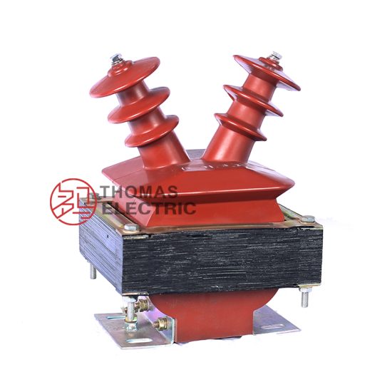
The DZJ-3 voltage transformer is a specialized instrument transformer designed for accurate voltage measurement, protection, and metering in 10kV medium-voltage power systems. As a critical component in electrical substations and distribution networks, it provides galvanic isolation between high-voltage primary circuits and low-voltage secondary instrumentation, ensuring operator safety and equipment compatibility. The DZJ-3 model adheres to national and international standards such as GB/T 20840 and IEC 61869, guaranteeing reliability under continuous operation and transient conditions. Its epoxy resin cast construction offers excellent insulation properties, mechanical strength, and resistance to environmental factors like humidity and pollution—making it suitable for both indoor and outdoor installations. This selection guide aims to assist engineers and procurement specialists in choosing the appropriate DZJ-3 configuration based on system requirements, accuracy needs, and application context. Understanding key parameters such as system voltage rating, transformation ratio, and accuracy class is essential to ensure optimal performance, regulatory compliance, and long-term operational stability.
System Voltage
The system voltage is a foundational parameter that determines the insulation level, dielectric strength, and overall design of the DZJ-3 voltage transformer. Rated for 10kV systems, the DZJ-3 is engineered to operate continuously at nominal voltages up to 10 kV (line-to-line) in three-phase AC networks with frequencies of 50 Hz or 60 Hz. However, it is crucial to distinguish between the nominal system voltage, maximum operating voltage, and the transformer’s insulation withstand capability. The DZJ-3 typically complies with a highest voltage for equipment (Um) of 12 kV, meaning it can safely endure transient overvoltages up to this level without insulation failure. This margin accommodates switching surges, lightning impulses, and temporary voltage rises inherent in distribution networks.
When selecting the DZJ-3, engineers must verify compatibility with the actual network voltage profile, including potential future upgrades or load variations. For instance, a system nominally rated at 10 kV may operate between 9.5 kV and 10.7 kV under normal conditions; the transformer must remain accurate and thermally stable across this range. Additionally, the DZJ-3 is designed for use in systems with specific earthing arrangements—commonly solidly grounded, resistively grounded, or ungrounded configurations. Each grounding method affects the voltage stress on the transformer during single-phase-to-ground faults, influencing the required insulation coordination and thermal duty cycle.
The table below summarizes key voltage-related specifications for the DZJ-3:
| Parameter | Value | Description |
|---|---|---|
| Nominal System Voltage (Un) | 10 kV | Standard operating line-to-line voltage |
| Highest Voltage for Equipment (Um) | 12 kV | Maximum voltage the insulation is designed to withstand |
| Power Frequency Withstand Voltage | 42 kV (1 min) | RMS voltage applied during factory testing |
| Lightning Impulse Withstand Voltage | 75 kV (peak) | Standard impulse test per IEC 60060 |
| Rated Frequency | 50/60 Hz | Compatible with standard utility frequencies |
Transformation Ratio
The transformation ratio of a voltage transformer defines the relationship between the primary (high-voltage) and secondary (low-voltage) windings. For the DZJ-3 10kV model, this ratio is critical for scaling down the system voltage to standardized, safe levels suitable for meters, relays, and monitoring devices—typically 100 V, 100/√3 V, or 110 V depending on regional standards and application type. The ratio is expressed as Vprimary : Vsecondary, such as 10,000 V : 100 V, which simplifies to 100:1. Accurate ratio selection ensures that connected instruments receive the correct input voltage for precise measurement and reliable protective relay operation.
DZJ-3 transformers often feature multiple secondary windings to serve different functions simultaneously—for example, one winding for metering (requiring high accuracy) and another for protection (designed to remain linear during fault conditions). Common configurations include single-secondary (e.g., 10/√3 kV / 100/√3 V) for phase-to-ground measurements in three-phase, four-wire systems, or dual-secondary setups (e.g., 10 kV / 100 V + 100 V) for combined metering and protection. The primary voltage may also be specified as phase-to-phase (10 kV) or phase-to-ground (10/√3 ≈ 5.77 kV), which directly influences the secondary output and must align with the system grounding scheme.
Selecting an incorrect transformation ratio can lead to significant errors: under-scaling may damage secondary devices, while over-scaling reduces measurement resolution and relay sensitivity. Moreover, the burden (load impedance) connected to the secondary must fall within the transformer’s rated capacity to maintain ratio accuracy. The DZJ-3 is typically rated for burdens ranging from 10 VA to 100 VA per winding, depending on accuracy class and application.
The following table illustrates typical transformation ratios available for the DZJ-3 10kV voltage transformer:
| Primary Voltage (kV) | Secondary Voltage (V) | Ratio | Application Context |
|---|---|---|---|
| 10 (phase-to-phase) | 100 | 100:1 | Three-phase, three-wire metering/protection |
| 10/√3 ≈ 5.77 (phase-to-ground) | 100/√3 ≈ 57.7 | 100:1 | Grounded wye systems, phase-to-neutral measurements |
| 10/√3 | 100/3 ≈ 33.3 | 173.2:1 | Residual voltage measurement for ground fault detection |
| 10 (phase-to-phase) | 100 + 100 | 100:1 (dual) | Separate metering and protection circuits |
| 10/√3 | 100/√3 + 100/√3 | 100:1 (dual) | Dual-function in grounded systems |
It is essential to coordinate the transformation ratio with the input requirements of downstream devices. For instance, energy meters in China commonly expect 100 V or 100/√3 V inputs, while some European systems use 110 V. Always consult device datasheets and local grid codes during selection.
Accuracy Class
Accuracy class defines the permissible error limits in voltage transformation under specified operating conditions, directly impacting measurement fidelity and protection reliability. The DZJ-3 voltage transformer is available in multiple accuracy classes per IEC 61869 and GB/T 20840 standards, typically ranging from 0.2 (high precision) to 3P or 6P (protection-oriented). Each class specifies maximum allowable ratio error (in percent) and phase displacement (in minutes) across a defined range of burdens and voltages (usually 80%–120% of rated voltage).
For metering applications—such as billing, revenue metering, or energy management—accuracy classes 0.2, 0.5, or 1.0 are preferred. Class 0.2 allows a maximum ratio error of ±0.2% and phase error of ±10 minutes at rated burden and voltage, ensuring minimal measurement uncertainty. In contrast, protection applications prioritize performance during fault conditions (e.g., 1.2× to 1.9× rated voltage), where maintaining linearity is more critical than absolute precision. Hence, protection classes like 3P (±3% ratio error up to 1.9× Un) or 6P (±6% up to 1.9× Un) are used, even though their steady-state accuracy is lower.
The DZJ-3 may feature windings with mixed accuracy classes—e.g., one secondary rated 0.5 for metering and another rated 3P for protection—enabling a single unit to serve dual roles. However, the total burden on each winding must not exceed its rated VA, and burdens must be purely resistive or inductive as specified; capacitive loads can destabilize performance. Temperature, frequency deviation, and aging also influence long-term accuracy, so proper derating and maintenance schedules are recommended.
The table below outlines common accuracy classes for the DZJ-3 and their typical applications:
| Accuracy Class | Max Ratio Error (%) | Max Phase Error (minutes) | Voltage Range | Primary Application |
|---|---|---|---|---|
| 0.2 | ±0.2 | ±10 | 80–120% Un | Precision metering, calibration labs |
| 0.5 | ±0.5 | ±20 | 80–120% Un | Commercial/industrial revenue metering |
| 1.0 | ±1.0 | ±40 | 80–120% Un | General monitoring, non-revenue metering |
| 3P | ±3.0 | Not specified | Up to 190% Un | Overvoltage protection, fault detection |
| 6P | ±6.0 | Not specified | Up to 190% Un | Basic protection in cost-sensitive systems |
5. Burden Calculation
The burden of a current transformer (CT) is the total impedance presented to its secondary winding, comprising connected devices (relays, meters, etc.) and interconnecting wiring. Accurate burden calculation is essential to ensure the CT operates within its accuracy class and avoids saturation during normal or fault conditions.
Burden is typically expressed in volt-amperes (VA) at a specified secondary current (usually 1 A or 5 A). The total burden \( Z_b \) is calculated as:
\[
Z_b = \frac{VA_{total}}{I_s^2}
\]
where \( I_s \) is the secondary current.
The total VA burden includes:
- Relay/meter burden: Provided by the manufacturer (e.g., 2.5 VA for a digital relay).
- Lead burden: Depends on wire length, cross-sectional area, and resistivity.
Lead resistance is calculated as:
\[
R_{lead} = \rho \cdot \frac{L}{A}
\]
where \( \rho \) = resistivity of copper (~0.0178 Ω·mm²/m at 20°C), \( L \) = total loop length (m), and \( A \) = conductor cross-section (mm²).
For a two-wire connection, total lead burden in VA is:
\[
VA_{lead} = I_s^2 \cdot 2R_{lead}
\]
Example: 5 A CT with 50 m one-way cable run (100 m loop), 4 mm² copper wire:
\[
R_{lead} = 0.0178 \cdot \frac{100}{4} = 0.445\ \Omega
\]
\[
VA_{lead} = 5^2 \cdot 2 \cdot 0.445 = 22.25\ \text{VA}
\]
This highlights why minimizing cable length and using adequate conductor size is critical.
| Component | Burden (VA) | Notes |
|---|---|---|
| Digital Protection Relay | 2.5 | Typical value at 5 A |
| Analog Ammeter | 3.0 | Moving-iron type |
| Lead Wiring (50 m, 2.5 mm²) | 8.9 | Calculated for 5 A system |
| Total Burden | 14.4 | Must be ≤ CT rated burden |
Exceeding the CT’s rated burden can cause ratio errors and phase shift, compromising protection coordination and metering accuracy. Always verify that the sum of all burdens remains below the CT’s nameplate rating (e.g., 15 VA, 30 VA).
6. Short-Circuit Considerations
Current transformers must withstand high short-circuit currents without damage and maintain performance during fault conditions. Two key parameters govern this behavior: short-time thermal current and dynamic (peak) current.
The short-time thermal current (\( I_{th} \)) is the RMS current the CT can carry for a specified duration (typically 1 s or 3 s) without exceeding temperature limits. It is usually expressed as a multiple of the rated primary current (e.g., 40 × In for 1 s).
The dynamic current (\( I_{dyn} \)) is the peak asymmetrical current the CT can endure mechanically without deformation or insulation failure. This value is often 2.5 times the RMS short-circuit current due to DC offset.
During a short circuit, the CT secondary must not saturate prematurely; otherwise, protective relays may fail to operate. To prevent saturation, the CT’s knee-point voltage (\( V_k \)) must exceed the voltage developed across the burden during the fault:
\[
V_k > I_{fault,sec} \cdot (R_{ct} + R_b)
\]
where \( R_{ct} \) is the CT secondary winding resistance and \( R_b \) is the total burden resistance.
Standards such as IEC 61869-2 specify test procedures for verifying short-circuit withstand capability. Designers must coordinate CT ratings with system fault levels derived from network studies.
| Parameter | Symbol | Typical Value | Standard Reference |
|---|---|---|---|
| Short-Time Thermal Current | \( I_{th} \) | 40 × In (1 s) | IEC 61869-2 |
| Dynamic Withstand Current | \( I_{dyn} \) | 100 × In | IEC 61869-2 |
| Maximum System Fault Level | \( I_{sc} \) | 31.5 kA RMS | Project specification |
| Required CT Rating | — | ≥ 31.5 kA / In | Must exceed system fault |
Failure to meet these requirements can result in insulation breakdown, open circuits (creating dangerous high voltages), or inaccurate relay operation. Always include safety margins—typically 10–20% above calculated fault levels.
7. Environmental Considerations
Environmental factors significantly influence CT selection, installation, and long-term reliability. Key considerations include ambient temperature, humidity, altitude, pollution, and exposure to chemicals or salt spray.
Ambient temperature affects insulation life and accuracy. Most CTs are rated for –5°C to +40°C. Operation outside this range may require derating or special designs (e.g., extended temperature range up to +70°C for outdoor substations in hot climates).
Altitude impacts dielectric strength. Above 1000 m, air density decreases, reducing insulation capability. Standards like IEC 60076 require derating or increased creepage distance for installations above 1000 m. For every 100 m above 1000 m, clearance distances should increase by approximately 1%.
Pollution degree determines required creepage distance. In coastal or industrial areas (pollution degree 3 or 4), CTs need enhanced insulation—typically ≥25 mm/kV for medium-voltage applications. Silicone rubber housings offer superior hydrophobicity and UV resistance compared to porcelain.
Humidity and condensation can lead to tracking and flashover. Sealed or gasketed enclosures with desiccants are recommended in high-humidity environments. Outdoor CTs should have drainage holes and hydrophobic sheds.
For indoor GIS or switchgear applications, compact epoxy-resin CTs are preferred. For outdoor use, polymer-housed or porcelain CTs with appropriate IP ratings (e.g., IP54 minimum) are standard.
| Environmental Factor | Impact on CT | Mitigation Strategy |
|---|---|---|
| High Ambient Temperature (>40°C) | Insulation aging, accuracy drift | Select CT with extended temp rating; provide shading/ventilation |
| Coastal (Salt Spray) | Corrosion, reduced surface insulation | Use silicone rubber housing; increase creepage distance |
| High Altitude (>1000 m) | Reduced dielectric strength | Apply altitude correction factor; increase clearances |
| Industrial Pollution | Surface tracking, flashover | Specify pollution degree 3/4; regular cleaning schedule |
Always consult local environmental data and applicable standards (IEC 60060, IEEE C37.20.2) during the design phase to ensure long-term operational integrity.
8. CT Selection and Verification Checklist
Use the following checklist during CT specification, procurement, and commissioning to ensure compliance with protection, metering, and safety requirements.
| # | Check Item | Verified? (Y/N) | Remarks |
|---|---|---|---|
| 1 | Primary current rating matches system load and fault level | e.g., 2000/5 A for 1800 A load | |
| 2 | Accuracy class meets application (e.g., 5P20 for protection, 0.5 for metering) | Confirm per IEC 61869 | |
| 3 | Total burden ≤ CT rated burden | Include leads, relays, meters | |
| 4 | Short-circuit withstand (Ith, Idyn) exceeds system fault level | Verify with network study | |
| 5 | Knee-point voltage sufficient to avoid saturation during faults | Calculate Vk requirement | |
| 6 | Environmental rating suitable (IP, temp, altitude, pollution) | Match site conditions | |
| 7 | Secondary terminals accessible and labeled clearly | Safety and maintenance | |
| 8 | Test certificates provided (ratio, polarity, insulation, burden) | Per IEC 61869-2 |
This checklist should be completed jointly by protection engineers, project managers, and commissioning teams. Any “No” response requires corrective action before energization. Documentation of verification supports future audits and maintenance planning.