Article Content
Introduction
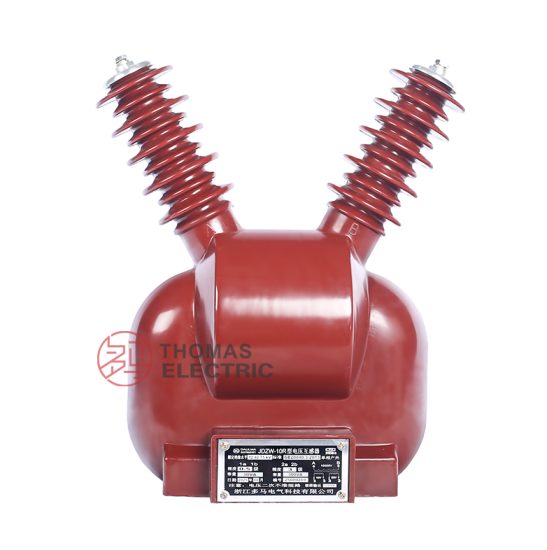
The JDZW-10R voltage transformer is a critical component in medium-voltage power systems, specifically engineered for accurate voltage measurement, protection, and metering applications at the 10 kV level. As a resin-insulated, outdoor-type instrument transformer, it offers high reliability, excellent dielectric strength, and resistance to environmental stressors such as moisture, dust, and temperature fluctuations. Designed in compliance with international standards including IEC 61869 and GB/T 20840, the JDZW-10R ensures consistent performance under normal and transient operating conditions. Its robust construction features a cast epoxy resin housing that provides superior mechanical strength and long-term insulation integrity, making it suitable for both indoor switchgear and outdoor substation installations. This selection guide aims to assist engineers, system designers, and procurement specialists in understanding key technical parameters—such as system voltage compatibility, transformation ratio options, and accuracy class requirements—to ensure optimal integration into power distribution networks. Proper selection not only enhances measurement precision but also safeguards downstream protective relays and metering devices from potential damage due to overvoltage or harmonic distortion.
System Voltage
The JDZW-10R voltage transformer is rated for use in three-phase AC power systems with a nominal system voltage of 10 kV. However, it is essential to distinguish between nominal system voltage, maximum system voltage, and equipment highest voltage for insulation coordination. The transformer is designed to operate continuously at a system frequency of 50 Hz (or optionally 60 Hz upon request) and can withstand temporary overvoltages as defined by relevant standards. The highest voltage for equipment (Um) is 12 kV, which represents the maximum RMS phase-to-phase voltage the transformer’s insulation system must endure without failure during normal operation or short-duration disturbances.
When selecting the JDZW-10R, users must verify that the local grid’s operating voltage falls within the permissible range. Continuous operation above 10.7 kV (i.e., 107% of nominal) may accelerate insulation aging or trigger thermal overload in connected burdens. Additionally, the transformer’s insulation level is coordinated with standard lightning impulse withstand voltage (75 kV peak) and power frequency withstand voltage (30 kV RMS for 1 minute), ensuring resilience against switching surges and atmospheric overvoltages.
| Parameter | Value | Description |
|---|---|---|
| Nominal System Voltage (Un) | 10 kV | RMS phase-to-phase voltage under normal operating conditions |
| Highest Voltage for Equipment (Um) | 12 kV | Maximum continuous system voltage the equipment is designed to handle |
| Power Frequency Withstand Voltage | 30 kV (1 min) | RMS voltage applied between windings and ground for insulation test |
| Lightning Impulse Withstand Voltage | 75 kV (peak) | Standard 1.2/50 µs impulse voltage for insulation coordination |
| System Frequency | 50 Hz (standard), 60 Hz (optional) | Must match grid frequency; affects core design and losses |
Incorrect matching of system voltage can lead to inaccurate secondary output, overheating, or insulation breakdown. Always confirm local utility specifications before installation.
Transformation Ratio
The transformation ratio of a voltage transformer defines the relationship between the primary (high-voltage) and secondary (low-voltage) windings. For the JDZW-10R, this ratio determines how the 10 kV system voltage is scaled down to a standardized, safe secondary voltage for instrumentation and protection circuits. The most common secondary voltages are 100 V, 100/√3 V, and 110 V (depending on regional standards), enabling compatibility with relays, meters, and monitoring systems worldwide.
The JDZW-10R typically offers multiple ratio configurations to accommodate different system grounding methods (e.g., solidly grounded, resistance-grounded, or ungrounded systems). In three-phase applications, the transformer may be connected in star (wye) or open-delta configurations, influencing the required secondary voltage per phase. For example, in a 10 kV system with a solidly grounded neutral, the phase-to-ground voltage is approximately 5.77 kV (i.e., 10 kV / √3). Thus, a transformation ratio of 10,000/√3 : 100/√3 simplifies to 100:1, yielding a secondary phase-to-neutral voltage of 57.7 V under balanced conditions.
Manufacturers often provide the JDZW-10R with dual or multi-tap secondary windings, allowing field adjustment of the ratio to compensate for line drop or calibration needs. Common standard ratios include:
- 10,000 V : 100 V (for phase-to-phase measurement)
- 10,000/√3 V : 100/√3 V (for phase-to-ground measurement in wye systems)
- 10,000 V : 110 V (used in some 60 Hz regions)
It is crucial to select the correct ratio based on the intended application. Metering circuits typically require precise scaling for revenue-grade accuracy, while protection relays may tolerate slight deviations but demand reliable performance during fault conditions. An incorrect ratio can cause relay misoperation or billing errors. Furthermore, the transformer’s burden rating (expressed in VA) must align with the total impedance of connected devices at the chosen ratio—higher burdens reduce accuracy and may saturate the core under fault currents.
| Primary Voltage Configuration | Secondary Voltage | Transformation Ratio | Typical Application |
|---|---|---|---|
| 10 kV (phase-to-phase) | 100 V | 100:1 | Phase-to-phase metering in delta systems |
| 10,000/√3 V ≈ 5774 V (phase-to-ground) | 100/√3 V ≈ 57.7 V | 100:1 | Phase-to-ground metering/protection in wye systems |
| 10 kV (phase-to-phase) | 110 V | 90.9:1 | Legacy or 60 Hz systems (e.g., parts of Asia, Americas) |
| 10,000/√3 V | 110/√3 V ≈ 63.5 V | 90.9:1 | Ground-fault detection in high-resistance grounded systems |
Note that the physical terminal markings on the JDZW-10R (e.g., A, N for primary; a, n for secondary) must correspond to the selected wiring diagram to avoid polarity errors. Always consult the manufacturer’s connection schematic before commissioning.
Accuracy Class
Accuracy class is a fundamental specification that defines the permissible error limits of a voltage transformer under specified load and operating conditions. For the JDZW-10R, accuracy class directly impacts its suitability for metering versus protection functions. Defined by IEC 61869-3 and GB/T 20840.3, accuracy classes indicate the maximum allowable composite error (including both ratio error and phase displacement) at a given percentage of rated voltage and burden.
The JDZW-10R is commonly available in multiple accuracy classes, such as 0.2, 0.5, 1, 3, and 3P/6P (the latter for protection). Classes 0.2 and 0.5 are typically used for precision metering and revenue billing, where even small errors can result in significant financial discrepancies. Class 1 may suffice for general industrial metering, while Class 3 is often reserved for less critical monitoring. Protection classes (3P, 6P) prioritize performance during abnormal conditions—such as voltage sags or swells—rather than steady-state precision. For instance, a 3P-class transformer must maintain defined error limits up to 190% of rated voltage to ensure reliable operation of overvoltage or undervoltage relays during faults.
Each accuracy class is associated with a standard burden (e.g., 10 VA, 30 VA, 50 VA) and a voltage range (typically 80–120% of rated voltage for metering classes). Exceeding the rated burden or operating outside the specified voltage range will degrade accuracy beyond the class guarantee. It is imperative to calculate the total connected burden—including wiring resistance—and ensure it does not exceed the transformer’s rated VA at the declared accuracy class.
| Accuracy Class | Max Ratio Error (%) | Max Phase Displacement (minutes) | Typical Burden (VA) | Primary Application |
|---|---|---|---|---|
| 0.2 | ±0.2 | ±10 | 10–30 | Revenue metering, calibration labs |
| 0.5 | ±0.5 | ±20 | 15–50 | Precision metering, tariff systems |
| 1 | ±1.0 | ±40 | 25–100 | General industrial metering |
| 3 | ±3.0 | Not specified | 30–100 | Non-critical monitoring |
| 3P | ±3.0 (at 5%–190% Un) | As per standard | 50–100 | Over/undervoltage protection |
| 6P | ±6.0 (at 5%–190% Un) | As per standard | 50–100 | Basic protection schemes |
When specifying the JDZW-10R, clearly state both the accuracy class and the associated burden. For dual-purpose units (e.g., one secondary for metering, another for protection), separate windings with independent accuracy ratings are often provided. Always validate that the selected class meets regulatory or utility requirements for your specific application.
5. Burden Calculation
The burden of a current transformer (CT) is the total impedance presented to its secondary winding, comprising connected devices (relays, meters, leads) and wiring. Accurate burden calculation ensures CTs operate within accuracy class limits under normal and fault conditions.
| Component | Typical Impedance (Ω) | Notes |
|---|---|---|
| Electromechanical Relay | 0.1 – 0.3 | Varies by model; consult manufacturer data |
| Digital Relay | 0.01 – 0.05 | Generally lower burden than electromechanical types |
| Analog Meter | 0.1 – 0.5 | Depends on full-scale current rating |
| Interconnecting Leads | 2 × (ρ × L / A) | ρ = resistivity (Ω·m), L = one-way length (m), A = cross-sectional area (m²) |
| Connections & Terminals | 0.02 – 0.05 | Includes contact resistance at terminal blocks |
Total burden \( Z_B \) is calculated as:
\[
Z_B = Z_{\text{relay}} + Z_{\text{meter}} + Z_{\text{leads}} + Z_{\text{connections}}
\]
For example, with a digital relay (0.03 Ω), 50 m of 4 mm² copper leads (ρ ≈ 1.72×10⁻⁸ Ω·m), and 0.03 Ω for connections:
\[
Z_{\text{leads}} = 2 \times \left( \frac{1.72 \times 10^{-8} \times 50}{4 \times 10^{-6}} \right) \approx 0.43\ \Omega
\]
\[
Z_B = 0.03 + 0.43 + 0.03 = 0.49\ \Omega
\]
This value must be less than the CT’s rated burden (e.g., 5P10 = 10 VA at 1 A → max burden = 10 Ω). Always include a 10–15% safety margin to account for aging and temperature effects.
6. Short-Circuit Considerations
Current transformers must withstand mechanical and thermal stresses during system short circuits without damage or loss of accuracy. Key parameters include symmetrical and asymmetrical fault currents, duration, and CT saturation characteristics.
| Parameter | Description | Design Impact |
|---|---|---|
| Symmetrical Fault Current | RMS value of AC component during fault | Determines thermal withstand capability |
| Asymmetrical Fault Current | Peak value including DC offset (up to √2 × 2 × Isym) | Governs mechanical force on windings |
| Fault Duration | Time until protective device operates (typically 0.1–3 s) | Affects thermal stress: I²t must be within CT rating |
| Knee Point Voltage (Vk) | Voltage at which CT core begins to saturate | Must exceed maximum voltage during fault: Vfault = Ifault × ZB |
| Accuracy Limit Factor (ALF) | Ratio of max accurate current to rated current (e.g., 10 for 5P10) | Ensure ALF × In > Ifault for protection CTs |
For instance, if a 1000 A system experiences a 25 kA fault for 0.2 s, a 1000/1 A, 5P20 CT has an ALF of 20 → max accurate current = 20,000 A. Since 25 kA > 20 kA, this CT may saturate. A 5P25 or higher class is required. Additionally, verify that Vk ≥ 25,000 A × 0.5 Ω = 12.5 kV—though impractical, this highlights the need for low-burden designs or high-Vk CTs in high-fault systems.
7. Environmental Considerations
Environmental factors significantly influence CT selection, installation, and long-term reliability. These include temperature extremes, humidity, altitude, pollution, and seismic activity.
| Factor | Impact | Mitigation Strategy |
|---|---|---|
| Ambient Temperature | Affects insulation life and accuracy; standard range: –25°C to +55°C | Select CTs rated for extended ranges (e.g., –40°C to +70°C) in harsh climates |
| Humidity & Condensation | Promotes corrosion and insulation degradation | Use sealed, gasketed enclosures with desiccants or conformal coatings |
| Altitude > 1000 m | Reduces air dielectric strength and cooling efficiency | Apply derating per IEC 61869-3; e.g., 1% per 100 m above 1000 m |
| Pollution (Dust, Salt, Chemicals) | Causes tracking, flashover, and terminal corrosion | Specify IP54 or higher ingress protection; use stainless steel hardware |
| Seismic Activity | Mechanical shock may damage core/windings | Choose CTs tested to IEEE 693 or IEC 60068-2-57 |
In coastal substations, salt fog necessitates epoxy-resin encapsulated CTs with silicone rubber sheds. In desert environments, UV-resistant housings prevent polymer degradation. Always verify compliance with local environmental standards (e.g., NEMA, IEC 60529) during procurement.
8. CT Selection and Installation Checklist
Use this checklist to ensure comprehensive evaluation during CT specification, procurement, and commissioning.
| Category | Verification Item | Status (✓/✗) |
|---|---|---|
| Application | Defined as metering or protection? | |
| Accuracy Class | Metering: 0.2/0.5; Protection: 5P/10P verified against system requirements? | |
| Burden | Total calculated burden ≤ CT rated burden with safety margin? | |
| Short-Circuit | ALF and Vk sufficient for max fault current and duration? | |
| Environmental | IP rating, temperature class, and material compatibility confirmed? | |
| Installation | Secondary leads properly sized, shielded (if needed), and grounded at one point? | |
| Testing | Excitation, polarity, ratio, and insulation resistance tests scheduled? | |
| Standards Compliance | Meets IEC 61869, IEEE C57.13, or applicable local standards? |
Complete this checklist during design review and site acceptance testing. Missing any item may lead to inaccurate measurements, relay misoperation, or premature failure. Retain signed copies in project documentation for audit and maintenance reference.