Article Content
IEC 61869-3 Certified 21kV Cast-Resin Voltage Transformer JDZW-20 for Metering & Protection Applications
Introduction to the JDZW-20 Voltage Transformer
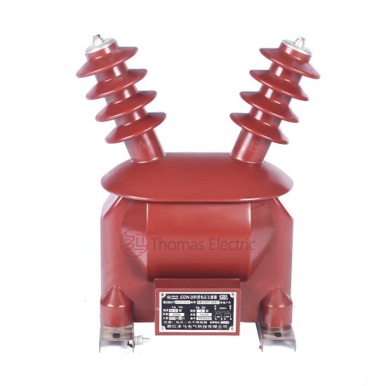
The JDZW-20 is a single-phase, outdoor-rated, cast-resin insulated electromagnetic voltage transformer (VT) designed for operation in 21 kV (IEC) / 20 kV (domestic) medium-voltage power systems. Engineered to meet the stringent requirements of IEC 61869-3 and GB/T 20840.3, this device provides accurate voltage transformation for metering, protection, and monitoring functions in utility substations, industrial plants, and renewable energy interconnection points. Its robust construction ensures long-term reliability under harsh environmental conditions while eliminating the fire and leakage hazards associated with traditional oil-filled units.
Operating Principle of Cast-Resin Insulation
Cast-resin insulation in the JDZW-20 employs vacuum pressure impregnation (VPI) technology using cycloaliphatic epoxy resin systems. The primary and secondary windings—wound on grain-oriented electrical steel (GOES) cores—are fully encapsulated under vacuum to eliminate air voids and moisture ingress. This monolithic structure provides uniform dielectric strength, high partial discharge inception voltage (>20 kV), and excellent thermal conductivity (0.8–1.2 W/m·K). Unlike oil-immersed designs, the solid resin matrix prevents tracking, corona formation, and degradation from UV exposure or pollution. The resin’s coefficient of thermal expansion closely matches that of copper and steel, minimizing mechanical stress during thermal cycling between –40°C and +40°C ambient temperatures.
Advantages Over Oil-Immersed Designs
The JDZW-20 eliminates flammability risks inherent in oil-filled VTs, making it suitable for indoor switchgear rooms and environmentally sensitive areas. With no oil to degrade or leak, maintenance intervals extend significantly—typically 10–15 years versus 3–5 years for oil types. The compact footprint (height ≈ 750 mm, weight ≈ 45 kg) reduces structural support requirements. Additionally, cast-resin units exhibit superior seismic performance (rated for 0.5g horizontal acceleration) due to their rigid internal structure. Partial discharge levels remain below 10 pC at 1.2 × Ur, ensuring decades of stable operation without insulation breakdown—a critical advantage over oil units prone to moisture absorption and sludge formation.
Typical Application Overview
In 20 kV distribution networks, the JDZW-20 interfaces with revenue meters (Class 0.2 or 0.5S), protective relays (e.g., overvoltage, undervoltage, directional earth-fault), and SCADA systems. It is commonly deployed on pole-mounted transformers, ring main units (RMUs), and gas-insulated switchgear (GIS) bays. For example, in a 20/0.4 kV urban substation, two JDZW-20 units (connected phase-to-ground) feed a three-phase metering cabinet via V-V connection, enabling accurate kWh billing while simultaneously supplying voltage signals to a feeder protection relay. Its outdoor rating (IP54) allows direct mounting on concrete pads without enclosures, reducing capital expenditure.
Technical Specifications
The JDZW-20 adheres to precise electrical and mechanical parameters defined by international standards. Below is a comprehensive specification table followed by service condition details.
| Parameter | Value |
|---|---|
| Primary Voltage (Ur) | 21/√3 kV (phase-to-ground) |
| Secondary Voltage | 100/√3 V or 110/√3 V (standard); 100 V (line-to-line optional) |
| Voltage Ratio | 21,000/√3 : 100/√3 = 210:1 (nominal) |
| Accuracy Class | Metering: 0.2, 0.5, 0.2S, 0.5S Protection: 3P, 6P |
| Rated Output (per burden class) | 10 VA (Class 0.2), 15 VA (Class 0.5), 30 VA (Class 3P) |
| Insulation Level (LI/AC) | 170 kV lightning impulse / 70 kV power frequency (1 min) |
| Short-Time Thermal Withstand | 1 second at 16 kA (symmetrical) |
| Frequency | 50 Hz or 60 Hz ±0.5 Hz |
| Core Material | Grain-Oriented Electrical Steel (GOES), M4 grade, 0.27 mm lamination |
| Insulation System | Cycloaliphatic epoxy resin, VPI process, UL 94 V-0 rated |
| Ambient Temperature Range | –40°C to +40°C |
| Altitude Limit | ≤1,000 m above sea level (derating required >1,000 m) |
| Pollution Degree | III (medium severity, per IEC 60664-1) |
Standard Service Conditions
The JDZW-20 is rated for continuous operation under standard service conditions per IEC 61869-3: ambient temperature from –40°C to +40°C, relative humidity up to 95% non-condensing, and altitude not exceeding 1,000 m. At altitudes between 1,000 m and 2,000 m, the power frequency withstand voltage must be reduced by 1% per 100 m increment. For example, at 1,500 m, the AC test voltage becomes 70 kV × (1 – 0.05) = 66.5 kV. Humidity resistance is validated through 168-hour damp heat testing (IEC 60068-2-78) with post-test insulation resistance >1,000 MΩ at 5 kV DC.
Electrical Performance Tolerances
Voltage error and phase displacement are tightly controlled within accuracy class limits. For Class 0.2S at 100% rated voltage and 25–100% burden, voltage error must be ≤±0.2%, and phase error ≤±10 minutes. At 1% burden (minimum load), error tolerance widens to ±0.75%. These tolerances ensure compliance with revenue metering regulations (e.g., MID Directive 2014/32/EU). The magnetizing current at rated voltage is typically <0.5% of rated primary current, minimizing core saturation during transient overvoltages up to 1.9 × Ur for 8 hours (per IEC 61869-3 Annex C).
Typical Applications
The JDZW-20 serves diverse roles across modern power infrastructure, leveraging its accuracy, durability, and compact form factor.
Substation Secondary Metering
In 20 kV primary substations, JDZW-20 units supply standardized 100/√3 V signals to multi-tariff energy meters for commercial billing. A typical configuration uses two VTs in open-delta (V-V) connection to derive three-phase voltages from a three-wire system. This setup achieves Class 0.2S accuracy even under unbalanced loading, critical for utilities recovering revenue from large industrial consumers. The low burden requirement (as low as 2.5 VA for modern digital meters) ensures minimal voltage drop in secondary cabling up to 100 m length.
Industrial Power Distribution
Within manufacturing facilities operating 20 kV internal networks, the JDZW-20 feeds protection relays such as SEL-351S or Siemens 7SJ62 for motor feeder overvoltage tripping. Its 3P accuracy class guarantees reliable operation during system disturbances—e.g., detecting a 10% sustained overvoltage within 0.5 seconds. The cast-resin housing resists chemical fumes and dust prevalent in cement plants or chemical processing sites, where IP54 ingress protection prevents conductive contamination on terminals.
Renewable Energy Integration
Solar farms and wind parks connecting to 20 kV grids use JDZW-20 VTs for grid-code compliance monitoring. They provide voltage signals to synchrophasors (PMUs) and anti-islanding relays, requiring phase displacement stability within ±5 minutes over –25°C to +55°C (achieved via low-thermal-expansion resin). During low-voltage ride-through (LVRT) events, the VT must accurately reflect grid voltage down to 15% of nominal for 150 ms—enabled by the GOES core’s high permeability at low flux densities.
Rural and Suburban Distribution Networks
Pole-mounted JDZW-20 units enable remote voltage monitoring in rural feeders via cellular-connected RTUs. Their lightweight design simplifies helicopter-assisted installation in mountainous regions. In suburban ring-main networks, they support automated sectionalizing by providing voltage presence signals to reclosers like NOJA OSM. The absence of oil eliminates environmental liability during pole-top faults, a key consideration for utilities managing thousands of distribution assets.
Compliance with International Standards
The JDZW-20 is engineered to satisfy both global and Chinese regulatory frameworks, ensuring interoperability and safety.
IEC 61869-3 Compliance Details
IEC 61869-3:2011 specifies performance, safety, and testing requirements for inductive voltage transformers. The JDZW-20 meets all clauses, including: rated insulation levels (Table 2), accuracy class definitions (Clause 5.3), temperature rise limits (<60 K for windings), and short-circuit withstand capability. Type tests include temperature rise (per Clause 7.3), lightning impulse (1.2/50 µs wave, 170 kV peak), and wet power frequency withstand (70 kV for 1 min after rain test). Routine tests—performed on every unit—include turns ratio verification (±0.2% tolerance), polarity check, and partial discharge measurement (<10 pC at 1.2 × Ur/√3).
GB/T 20840.3 Alignment
China’s national standard GB/T 20840.3-2013 aligns closely with IEC 61869-3 but includes additional requirements for domestic grids. Key differences include: mandatory 1-minute power frequency test at 80 kV (vs. 70 kV IEC) for 20 kV class, and stricter partial discharge limits (<5 pC at 1.2 × Ur). The JDZW-20 exceeds both by design, featuring reinforced resin barriers between windings and grounded electrostatic shields to suppress field gradients. Certification by China National Accreditation Service (CNAS) laboratories validates compliance for State Grid and China Southern Grid procurement.
Testing and Certification Requirements
Full type testing requires third-party laboratory validation (e.g., KEMA, CESI, or SGCC-certified labs). Tests span electromagnetic compatibility (IEC 61000-4 series), seismic resilience (IEEE 693), and fire behavior (IEC 60695 glow-wire test at 850°C). Each production batch undergoes sample testing per ISO 2859-1 (AQL 1.0). Certificates include IEC 61869-3 Type Test Report, GB/T 20840.3 Conformity Certificate, and RoHS compliance documentation.
On-Site Testing Procedures
Post-installation verification ensures the JDZW-20 performs within specifications before energization.
Insulation Resistance Test
Using a 5 kV megohmmeter, measure insulation resistance between primary winding and ground, and between secondary windings and ground. Acceptance criterion: ≥1,000 MΩ at 20°C. Correct for temperature using RT2 = RT1 × 2(T1–T2)/10. Low readings (<100 MΩ) indicate moisture ingress or resin cracking, requiring drying or replacement.
Turns Ratio Test
Apply 100–200 V AC to the primary and measure secondary voltage. Calculate ratio = Vp/Vs. Tolerance: ±0.2% of nominal (210:1). For 100/√3 V secondary, expected Vs = 200 / 210 ≈ 0.952 V. Deviations >0.4% suggest winding shorts or incorrect tap selection.
Polarity Test
Verify reducing polarity per IEC 61869-3 Figure 4. Connect a 6–12 V battery momentarily between primary terminals H1(+) and H2(–). Observe secondary voltage spike on a DC voltmeter connected to X1(+) and X2(–). A positive deflection confirms correct polarity. Incorrect polarity causes metering errors and relay misoperation.
Power Frequency Withstand Voltage Test
Apply 70 kV RMS (50 Hz) between primary and grounded tank/secondary for 1 minute. Use a calibrated test transformer with overcurrent trip (≤100 mA). No flashover or disruptive discharge is permitted. For field tests, reduce voltage to 80% (56 kV) if equipment limitations exist, per IEC 60270 guidance.
Open-Circuit Characteristic Test
Gradually increase primary voltage from 0 to 1.5 × Ur/√3 (≈18.2 kV) while measuring secondary voltage and excitation current. Plot Vs vs. Imag. Knee point should exceed 1.5 × Ur; excessive current (>1% of rated) indicates core saturation or inter-turn faults. This test validates magnetic circuit integrity before commissioning.
Preventive Maintenance Guide
Proactive maintenance extends service life beyond 30 years and prevents unplanned outages.
Periodic Inspection Protocol
Annual visual inspections check for: surface cracks in resin (use dye penetrant if suspected), terminal corrosion (clean with isopropyl alcohol), and loose hardware (torque to 25 N·m). Verify grounding continuity (<0.1 Ω resistance). In coastal areas, wash housing with deionized water to remove salt deposits. Thermographic scans during peak load detect abnormal hotspots (>10 K above ambient) indicating internal defects.
Maintenance Intervals and Fault Diagnosis
Follow this schedule:
| Interval | Action |
|---|---|
| 1 year | Visual inspection, IR thermography, insulation resistance |
| 5 years | Full electrical tests (ratio, polarity, PD measurement) |
| 10 years | Dielectric frequency response (DFR) analysis to assess aging |
Common faults include: (1) Secondary open-circuit—causes core saturation and overheating; install shorting links during meter replacement. (2) Resin delamination—detected via ultrasonic testing; replace if crack depth >2 mm. (3) Moisture ingress at terminal seals—repack with silicone grease (Dow Corning 4).
Conclusion
The JDZW-20 cast-resin voltage transformer represents a benchmark in medium-voltage instrumentation, combining IEC 61869-3 and GB/T 20840.3 compliance with field-proven reliability. Its cycloaliphatic epoxy resin insulation system, coupled with GOES silicon steel cores, delivers exceptional accuracy (Class 0.2S), robust environmental resistance (–40°C to +40°C, IP54), and immunity to fire hazards. Designed for 21 kV (IEC) / 20 kV (domestic) systems, it supports critical applications from revenue metering to renewable integration with minimal lifecycle costs. Rigorous type testing—including 170 kV lightning impulse and 70 kV power frequency withstand—ensures decades of maintenance-free operation. With an expected service life of 25–30 years under standard conditions, the JDZW-20 offers utilities and industrial operators a technically superior, future-proof solution for voltage sensing in evolving power networks. Its compact, oil-free design aligns with global sustainability goals while meeting the highest standards of metrological integrity and system protection reliability.
Q1: What is the difference between 20kV and 21kV ratings for the JDZW-20?
The 20 kV designation refers to the nominal system voltage used in domestic (e.g., Chinese) power networks, while 21 kV is the IEC-standardized highest voltage for equipment (Um). The JDZW-20 is designed for Um = 21 kV, ensuring compatibility with international grids and providing a 5% overvoltage margin for 20 kV systems.
Q2: Can the JDZW-20 be used indoors?
Yes. Although rated for outdoor use (IP54), the JDZW-20’s non-flammable cast-resin construction makes it suitable for indoor installations, including metal-enclosed switchgear. Ensure adequate clearance (≥125 mm) around the unit for ventilation and arc flash mitigation.
Q3: What burden values are compatible with Class 0.2S accuracy?
For Class 0.2S, the JDZW-20 maintains accuracy with burdens between 2.5 VA and 100% of rated output (typically 10 VA). Operation below 2.5 VA may exceed error limits; consult the accuracy envelope curve in the test report.
Q4: How is partial discharge measured during factory testing?
Per IEC 60270, partial discharge is measured at 1.2 × Ur/√3 (≈14.5 kV) using a coupling capacitor and quadrupole detector. The JDZW-20 consistently achieves <5 pC, well below the 10 pC IEC limit.
Q5: Is the JDZW-20 suitable for 60 Hz systems?
Yes. Core lamination thickness (0.27 mm) and resin formulation are optimized for both 50 Hz and 60 Hz operation. Magnetizing current remains <0.6% of rated at 60 Hz, ensuring accuracy class compliance.